Numerical Analysis of Natural, Mechanical, and Hybrid Ventilation in a Cadmium Telluride Photovoltaic Greenhouse for Tomato Production in Uganda
Abstract:
Controlled-environment agriculture has emerged as a promising approach for improving food security and climate resilience in semi-arid regions. Among recent innovations, Cadmium Telluride (CdTe) photovoltaic-integrated greenhouses offer the dual benefit of renewable energy generation and sufficient photosynthetically active radiation for crop growth. However, the thermal and microclimatic performance of ventilation systems in such greenhouses remains insufficiently investigated, particularly under sub-Saharan African conditions. In this study, a gable-roof CdTe photovoltaic-integrated greenhouse structure (3.6 m × 2.25 m × 2.0 m) was numerically analyzed using a validated three-dimensional Computational Fluid Dynamics (CFD) model developed in SolidWorks Flow Simulation. Three ventilation strategies—natural, mechanical, and hybrid ventilation—were evaluated for their effects on thermal regulation and airflow distribution. Natural ventilation employed top and side vents equivalent to 10% of the floor area, while mechanical ventilation used four 13 W fans providing 40 air changes per hour (ACH). The hybrid system combined natural and mechanical ventilation. A Design of Experiments (DoE) framework was further applied to evaluate interactions among airflow, temperature, humidity, and energy demand. Experimental validation using a full-scale prototype at Busitema University showed strong agreement between simulated and measured temperatures, with a Coefficient of Determination (R2) of 0.92, a Root Mean Square Error of 1.18 °C, and a Normalized Mean Bias Error of +1.3%. The hybrid ventilation system achieved the best performance, maintaining greenhouse temperatures within the optimal range of 21–27 °C. Furthermore, the greenhouse energy and water requirements were estimated, indicating that stable tomato production could be sustained using a heating capacity of 0.5 kW and a daily irrigation demand of 44 L for 24 tomato plants operated under six precision pulse-irrigation cycles per day. These findings demonstrate that CdTe photovoltaic-integrated greenhouses can effectively balance energy efficiency and crop productivity, thereby providing a scalable and sustainable framework for protected agriculture in developing countries and semi-arid environments.
1. Introduction
Today, agriculture is increasingly relying on controlled-environment agriculture [1]. This is aimed at creating stable crop growing conditions, such as light, temperature, and water for year-round growth, with reduced resource use and climate risks and increased crop yield by enabling urban agriculture and mitigating climate change. Water-sensitive crops like tomatoes need to be grown in greenhouses with a customized microclimate [2], [3] because tomato plants’ growth and their pollination can be adversely affected by weather change [4]. Regardless of the climate control required for growing crops, traditional greenhouses are energy-intensive. New innovations such as closed and semi-closed greenhouses can solve this problem and improve energy efficiency and management, making sustainable agriculture possible [5].
Thin-film Cadmium Telluride (CdTe) PV glazing integration into greenhouse structures represents a novel approach to supporting sustainable agricultural practices [6], making it particularly relevant for sun-rich regions such as Uganda. State-of-the-art greenhouse operations consume a lot of energy, but Luo et al. [7] optimized the greenhouse microclimate for increased yield, especially for tomato growing, to address the energy demands of these operations. Several studies [8], [9], [10], [11] have indicated that, beyond its role in converting sunlight into electricity, photovoltaic glazing on greenhouses can stabilize canopy temperatures, especially during times of intense sunlight, by acting as a ultraviolet-filter or a shade, and mitigate heat stress on crops or plants, particularly in arid or sun-intensive climates. However, it should be noted that when shades are put on the greenhouse, fruit development delays [12], which reduces crop yield by 15–26% [13]. The energy generated by the photovoltaic system can overcompensate for these disadvantages, demonstrating a clear economic advantage [13]. Therefore, to ensure economic viability and competitiveness in greenhouse production, integrating photovoltaic technology is essential for sustaining crop yield when compared with conventional greenhouse systems [14]. This integrated system is designed to generate electricity for powering greenhouse environmental control components and actuators, thereby establishing a more energy-efficient and semi-autonomous crop production environment.
Given the benefits of integrated greenhouse systems, the importance of controlled-environment agriculture becomes particularly significant in semi-arid regions such as northeastern Uganda. The controlled-environment agriculture in greenhouses allows for precise control of the internal microclimate, which is very important for optimizing plants’ photosynthesis and transpiration while maintaining optimal environmental conditions. Natural ventilation is widely recognized as the most effective and energy-efficient technique for regulating greenhouse microclimates, which majorly rely on wind and buoyancy force to manage the microclimate without added electrical cost. However, natural ventilation depends on outside ambient conditions, which makes it difficult to control in a greenhouse setting. Mechanical ventilation may be an effective method for improving climate control in screened greenhouses. Nevertheless, mechanical ventilation systems have generally been less widely adopted than natural ventilation systems because of their higher energy consumption and maintenance requirements [15]. Current studies have revealed a notable gap in the development of hybrid ventilation systems (combined natural and forced ventilation) specifically tailored for greenhouse environments. In addition, there is a lack of comprehensive guidelines addressing critical design parameters such as greenhouse envelope sizing, vent configurations, and overall structural analysis, all of which are essential for functional greenhouse construction and the optimization of tomato production systems.
It is also apparent that the design and implementation of new greenhouse projects without prior performance prediction has frequently resulted in system failures and unacceptable outcomes [16]. Those premature failures not only result in project delays but are also very costly, leading to resource losses [17]. To prevent or mitigate these risks in current engineering practice, practicing engineers now rely on advanced methods, including predictive tools such as Computational Fluid Dynamics (CFD), to simulate and analyze system performance under a range of real-world operating conditions. CFD is a proven tool for analyzing greenhouse climates, and therefore, in modern product design and engineering, simulation currently plays a major part, with many engineering firms now shifting from destructive, physical testing to testing in a digital representation of the real-world environment [18].
This study aims to design and analyze three distinct ventilation configurations using CFD and to validate the resulting three-dimensional CFD model against a fabricated CdTe greenhouse prototype specifically developed for tomato production. The analysis focuses on thermal flow and internal flow pattern within the designed greenhouse concept, with validation achieved through the use of a full-scale, fabricated prototype. The analysis helps to evaluate the greenhouse’s ability to maintain the optimal microclimate essential for tomato production. It also provides a sustainable approach to enhancing food security by minimizing risks, time, and costs. By identifying flaws and bottlenecks by testing various project scenarios, the analysis facilitates early project adjustments in a safe virtual environment prior to the construction of the physical project.
While the existing literature has comprehensively covered the traditional silicon-based photovoltaics and natural and forced ventilation systems, this study offers three distinct contributions to the field of controlled-environment agriculture. First, it investigates the integration of semi-transparent CdTe photovoltaic glazing in greenhouse technology, moving beyond opaque solar technologies to balance electrical yield while providing the required specific photosynthetically active radiation for tomato varieties in equatorial regions. Secondly, it bridges a critical research gap in greenhouse ventilation systems through developing and analyzing a hybrid configuration system (combined natural and forced ventilation) specifically optimized for high thermal loads of semi-arid tropical climates. Thirdly, unlike the previous research that remains purely numerical, this work presents a comprehensive CFD-experimental validation loop by using a 1:1 scale fabricated prototype in Uganda. The study, therefore, provides a validated engineering blueprint for the energy autonomous greenhouse systems that reconcile the competing demands of the energy-food nexus in sub-Saharan Africa.
2. Materials and Methods
The study methodology of this study involved an in-depth analysis of the proposed site environmental data (Busitema University), followed by a detailed design and dimensioning of the tomato greenhouse. Internal CFD analysis for three greenhouse models was performed, that is, natural, mechanical, and hybrid ventilation, and a parametric study was conducted using the Design of Experiments (DoE) tool in SolidWorks flow simulation, aiming to determine the most effective and efficient design model.
A CdTe-integrated greenhouse was designed, fabricated, and installed at Busitema University in Busia District at coordinates 0.46°N, 34.1°E. The region has a tropical climate, with an average mean annual temperature range of 22 °C to 30 °C and solar radiation of 5.1 to 6.0 kWh/m$^2$ per day [19], [20]. This site was chosen to represent typical conditions for small-scale tomato production in Uganda, and this provides a large solar energy potential for the CdTe photovoltaic system integrated into the greenhouse.
Several critical assumptions (Table 1) were made to design and determine the appropriate size of the greenhouse.
Description | Parameter |
|---|---|
Greenhouse geometry (gable type) | Length = 3.60 m, width = 2.253 m, height = 2.0 m, roof pitch = 20° |
Option A (70% transparency): Thin-film CdTe roof glazing | Active fraction = 30%, nominal power = 28 W, efficiency = 12%, and overall heat transfer coefficient (U-value) = 2.5 W/m$^2$·K |
Option B (60% transparency): Thin-film CdTe roof glazing | Active fraction = 40%, nominal power = 38 W, efficiency = 12%, U-value = 2.5 W/m$^2$·K |
Polycarbonate sheet (side wall glazing) | U-value = 5.0 W/m$^2$·K (single high-density polyethylene film) |
Busia’s average solar resource | 5.1 kWh/m$^2$·day [19], [20] |
The greenhouse floor area $A_{\mathrm{f}}$, volume $V$, roof area $A_{\mathrm{roof}}$, wall areas $A_{\mathrm{walls}}$ and the total envelope area was obtained from Eqs. (1)–(6):
where, $L$ is the total length, and $W$ is the width of the greenhouse. Therefore:
$$A_{\mathrm{f}} = 3.6 \times 2.253 = 8.1108\ \text{m}^2 $$
where, $h_{\mathrm{avg}}$ is the average internal greenhouse height. Therefore:
$$ V = 8.110 \times 2.0 = 16.22\ \text{m}^3 $$
For the gable roof, consisting of two identical sloped surfaces, the roof slope factors were defined as:
$$ \text{roof slope factors} = \frac{1}{\cos(\theta)}, \quad \text{with } \theta = \text{pitch angle} $$
But
$$L \times W = A_{\mathrm{f}}, \quad s = \frac{1}{\cos(20^\circ)} $$
Therefore:
$$ A_{\mathrm{roof}} = 8.1108 \times 1.0642 = 8.633\ \text{m}^2 $$
The wall area $A_{\mathrm{walls}}$ is given as:
$$ \text{Perimeter} = 2(3.6 + 2.253) = 11.706\ \text{m} $$
$$A_{\mathrm{walls}} = 11.706 \times 2 = 23.412\ \text{m}^2 $$
The total envelope area $A_{\mathrm{env}}$ for conduction is as follows:
Therefore:
$$ A_{\mathrm{env}} = 8.633 + 23.412 = 32.045\ \text{m}^2 $$
$\bullet$ Fan Airflow and Its Capacity
As a rule of thumb, the air changes per hour (ACH) in warm climates for tomato growing should be between 40 and 60 [23]. Therefore, the fan airflow was then obtained from Eq. (7):
where, $\dot{V}$ is the airflow ($\text{m}^3/\text{s}$), and $V$ is the volume of the greenhouse ($\text{m}^3$). The design target for a tomato greenhouse in a warm climate is 40 ACH for the daytime ventilation target. For this small volume:
$$ \dot{V} = \frac{40 \times 16.22}{3600} = 0.180\ \text{m}^3/\text{s} $$
$\bullet$ Minimum Fan Power Required
The rough electrical power estimate was obtained from Eq. (8) [24]:
where, $\rho$ is the density of air (1.2 kg/m$^3$), $\Delta_p = 30$ Pa for a small greenhouse, $\eta_{\mathrm{fan}} = 0.5$; therefore, the fan's electric power was obtained.
$$ P_{\mathrm{fan}} = \frac{1.2 \times 0.18 \times 30}{0.5} = 13\ \text{W} $$
For this study, four fans were selected, two inlet and two exhaust, each equipped with a controller set to operate at a low speed of approximately 1000 rpm. This configuration was chosen to ensure equilibrium between incoming and outgoing air, preventing pressure imbalances and promoting uniform airflow distribution across the greenhouse. To allow margins, a practical choice range of 25 to 50 W small fans was used for the study. The first step was to determine the amount of air that would be circulated by the exhaust fans. This number is based on the rate required to replace all of the air in the greenhouse. However, a practical guideline for cooling is to aim for one complete air exchange every minute [25], and therefore, using Eq. (7), the airflow rate per hour was obtained.
$$ \dot{V} = \frac{1 \times 16.22\ \text{m}^3}{3600\ \text{s}} = 16.22\ \text{m}^3/\text{hr} = 0.270\ \text{m}^3/\text{min} $$
As the specifications for fans are measured in cubic feet per minute, the airflow rate was converted from cubic meters per minute to the necessary cubic feet per minute using a conversion factor (1 m$^3$ = 35.3147 ft$^3$).
Application of the conversion resulted in the following:
$$ 0.270\ \text{m}^3/\text{min} \times 35.3147\ \text{ft}^3/\text{m}^3 = 9.535\ \text{ft}^3/\text{min} $$
$\bullet$ Side and Roof Vents
When it comes to natural ventilation, two main factors influence the airflow: wind speed and stack effect, also known as buoyancy [26]. Therefore, the airflow rate per vent was obtained using Eq. (9):
where, $A_u$ is the total effective vent area (m$^2$), $u$ is the wind speed at ridge height (m/s), and $C_u$ is the discharge pressure coefficient (0.2–0.35 for typical vents) [27]. As for typical breeze for the proposed site, $u = 2$ m/s, and $C_u = 0.25$.
Therefore,
$$ \dot{V}_N = 0.25 \times 0.405 \times 2 = 0.203\ \text{m}^3/\text{s} \quad \text{(for each vent)} $$
A general guideline for designing effective natural ventilation is that the unventilated area should be at least 10–15% of the floor area [28]. Using Eq. (1), the greenhouse floor area was 8.1108 m$^2$. Therefore, 10% equated to 0.811 m$^2$, and 15% equated to 1.217 m$^2$. The vent sizes at 10% and 15% of the greenhouse floor area are presented in Table 2.
Description | 10% of Floor Area | 15% of Floor Area |
|---|---|---|
Floor area (m$^2$) | 8.1108 | 8.1108 |
Total vent area (m$^2$) | 0.8110 | 1.2166 |
Ridge vent area (50% allocation) (m$^2$) | 0.4050 | 0.6083 |
Ridge vent height (opening) along a 3.6 m ridge | 0.405/3.6 = 112 mm | 0.6083/3.6 = 169 mm |
Side vents combined (both sides) area (m$^2$) | 0.4050 | 0.6083 |
Side vents per side (m$^2$) | 0.405/2 = 0.2025 m$^2$ | 0.6083/2 = 0.30415 m$^2$ |
Side vent height along 3.6 m greenhouse length | 0.2025/3.6 = 0.056 m | 0.30415/3.6 = 0.0845 m |
The following assumptions were adopted:
$\bullet$ Plant density ($D$): 3 plants/m$^2$
$\bullet$ Reference evapotranspiration ($ET_o$): 4.5 mm/day (typical warm equatorial day, tomatoes at full cover) [29]
$\bullet$ Crop coefficient ($K_c$): 1.1
$\bullet$ Application efficiency ($\eta_{\mathrm{app}}$): 0.9 for drip irrigation
To estimate the water requirement in Eq. (14), the reference evapotranspiration was first calculated using Eq. (10), followed by determining the daily water needed per area for tomato crops using Eq. (11). This included figuring out the daily water usage per plant using Eq. (12), and the total number of plants to be cultivated using Eq. (13) [30], [31], [32].
Daily water per area:
where, $\text{ET}_o$ is the reference evapotranspiration, $K_c$ is the crop coefficient (stage-dependent), and $\eta_{\mathrm{app}}$ is the application efficiency.
Therefore:
$$ \text{ET}_c = 4.5 \times 1.1 = 4.95\ \text{mm}/\text{day} $$
If plant density is $D = 3$ plants/m$^2$, then the daily water in liters per plant per day ($D_W$) was obtained from Eq. (12):
$$ D_W = \frac{4.95 \times 1}{3 \times 0.9} = 1.833\ \text{L}/\text{plant/day} $$
Plant density is 3 plants/m$^2$, and the greenhouse floor area ($A_{\mathrm{f}}$) is 8.1108 m$^2$. The total number of plants ($P_{\mathrm{total}}$) in the greenhouse was obtained as follows:
where, $D$ is the plant density (3 plants/m$^2$), and $A_{\mathrm{f}}$ is the floor area of the greenhouse.
$$ P_{\mathrm{total}} = 3 \times 8.1108 = 24\ \text{plants} $$
Therefore, the total daily greenhouse water demand for irrigation ($D_{\mathrm{irrig}}$) per day was obtained from Eq. (14):
$$ D_{\mathrm{irrig}} = 24 \times 1.833 = 44\ \text{L}/\text{day} $$
Two emitters per plant with 2 L per hour each were used. The total emitter flow per plant is 4 L per hour. Then, the required runtime ($R_T$) per plant per day was obtained from Eq. (15).
$$ R_T = \frac{1.833}{4}\ \text{h} = 0.458\ \text{h} = 28\ \text{min/day} $$
Split pulsed irrigation was adopted in this study due to its effectiveness in reducing runoff and enhancing root-zone aeration. The system was programmed to deliver six pulses per day at a three-hour interval (06:00, 09:00, 12:00, 15:00, 18:00, and 21:00). Each pulse lasted approximately 4.7 minutes, calculated as the total transmitter operating time (28 min/day) divided by six pulses. From the recommendations of Abdelghany [33], irrigation was restricted to daytime hours to avoid nighttime watering when relative humidity (RH) is high, thereby minimizing evaporative losses and reducing the risk of disease development. According to Rodowick [34], watering should be 30–50% of full capacity, that is 0.75–1.25 L/plant/day delivered in short cycles per day, and each lasting between 2 and 4 minutes to maintain a moist substrate without oversaturation, which is critical given the lower demand but high frequency of water uptake at this stage. In contrast, during the fruit stage, transpiration rates increase markedly in hot months due to elevated temperatures and reduced humidity. Water demand rises to 3–4 L per plant per day, which requires more frequent but smaller irrigation doses. Six pulses per day were selected for this study, rather than large infrequent doses [35]. This approach helps in matching the increased evapotranspiration in the greenhouse and ensures continuous water availability for cooling tomato plants and facilitating nutrient uptake.
The following assumptions were adopted:
$\bullet$ Greenhouse volume ($V$): 16.22 m$^3$ using Eq. (2)
$\bullet$ Typical indoor temperature of the air used for calculations: 25 $^{\circ}\mathrm{C}$
$\bullet$ Atmospheric pressure ($P$): 101.325 kPa
$\bullet$ The density of air ($\rho$) at 25 $^{\circ}\mathrm{C}$: 1.184 kg/m$^3$
$\bullet$ The optimal RH range for tomato growing in the greenhouse: 50%–70%
$\bullet$ As for mechanical ventilation design, the airflow ($\dot{V}$) is 0.180 m$^3$/s with 40 ACH using Eq. (7)
$\bullet$ Tomato canopy for a fully grown plant: 1.2 m above the floor
Therefore, the water vapor to raise the required optimal RH for tomatoes was obtained from Eq. (16).
where, $w$ is the humidity ratio (kg water per kg dry air) and is determined as the mass of water vapor per unit mass of dry air [36]; $P$ is the atmospheric pressure; and $p_v$ is the vapor pressure. The vapor pressure $p_v$ was obtained using Eq. (17) [37].
According to the Engineering ToolBox [37] (water saturation pressure versus temperature tables), the saturation vapor pressure $p_{\mathrm{sat}}$ at 25 \(^\circ\)C is 3.169 kPa. This value was subsequently adopted in the following subsections.
Using Eq. (17), the vapor pressures were computed at a RH of 50% ($p_{v,1}$) and 75% ($p_{v,2}$), respectively.
$$ p_{v,1} = 0.50 \times 3.169 = 1.5845\ \text{kPa} $$
$$ p_{v,2} = 0.75 \times 3.169 = 2.37675\ \text{kPa} $$
Using Eq. (16), the humidity ratios at $p_{v,1}$ and $p_{v,2}$ were obtained.
$$ w_1 = 0.622 \times \left( \frac{1.5845}{101.325 - 1.5845} \right) = 0.009887\ \text{kg}/\text{kg} = 0.00989 $$
$$ w_2 = 0.622 \times \left( \frac{2.37675}{101.325 - 2.37675} \right) = 0.01494\ \text{kg}/\text{kg} = 0.01494 $$
The mass of dry air inside the greenhouse $m_{\mathrm{air}}$ was obtained using Eq. (18), and the mass of water vapor was calculated using Eq. (19).
$$ m_{\mathrm{air}} = (1.184\ \text{kg}/\text{m}^3 \times 16.22\ \text{m}^3) = 19.2045\ \text{kg} $$
The mass of water vapor needed was obtained as follows:
where, $\Delta w$ is the change in the humidity ratio, i.e., $\Delta w = w_2 - w_1$.
Therefore:
$$ m_{\mathrm{water\_vapor}} = 19.2045 \times (0.01494 - 0.009887) = 0.09704\ \text{kg} = 0.097\ \text{L} $$
To raise the RH from 50–75% at 25 \(^\circ\)C throughout the greenhouse, a one-time injection of 0.097 L of water vapor is required. Since the amount to increase the RH is quite small, the maintenance load due to ventilation losses is substantial and must be calculated.
With ventilation, the incoming outside air has a lower RH during daytime, which reduces the humidity inside the greenhouse. Therefore, the system must replace the water vapor at the same rate as it is removed during ventilation. Therefore, if the RH falls too low, i.e., $<$55% for tomatoes, this will cause excess transpiration stress on plants, stomatal closure, and slowing of photosynthesis, and could increase the risk of blossom end rot and poor tomato fruit setting [38]. To determine the moisture loss ($\dot{m}_{\mathrm{water}}$), the air mass flow ($\dot{m}_{\mathrm{air}}$) exchange should be computed first, and this was obtained using Eq. (20), and the rate of moisture loss was calculated using Eq. (21).
where, $\rho$ is the density of air, and $\dot{V}$ is the airflow. Using Eq. (7), it was obtained that $\dot{V} = 0.180\ \text{m}^3/\text{s}$ at 40 ACH.
$$ \dot{m}_{\mathrm{air}} = 1.184\ \text{kg}/\text{m}^3 \times 0.180\ \text{m}^3/\text{s} = 0.21312\ \text{kg/s} $$
Assuming the outside RH is 50% and the inside RH is 75%, using Eq. (16), $w_{\mathrm{outside}} = w_1 = 0.009887\ \text{kg}/\text{kg}$, and $w_2 = w_{\mathrm{inside}} = 0.01494\ \text{kg}/\text{kg}$ were obtained.
Therefore:
$$ \dot{m}_{\mathrm{water}} = 0.21312 \times (0.01494 - 0.009887) = 0.001077\ \text{kg}/\text{s} $$
This was converted into the following:
$$ = 0.001077 \times 3600 = 3.8769\ \text{kg}/\text{h} = 3.9\ \text{L}/\text{hr} $$
Therefore, the system has to supply 3.9 L per hour of water vapor continuously to maintain the humidifier flow hold of 75% RH while ventilating at 40 ACH at an outside RH of 50%. Since the system was designed to ventilate at 40 ACH during the hottest daytime, a humidifier capacity ($\geq$5 L per hour) was chosen to cover for inefficiency margins (droplet runoff and control).
The goal was to evaporate the water into the greenhouse air before it touches the tomato canopy leaves to avoid leaf wetting and disease that could be caused by the same, and to ensure uniform mixing to avoid spraying onto the CdTe photovoltaic modules. Schnelle et al. [39] recommended mounting the humidifier at least 0.3–0.6 m above the plant canopy to allow sufficient time for the water droplets to evaporate and mix into the air before reaching the leaves. This study assumed a plant canopy height of 1.2 m above ground for both the Moneymaker and Tengeru tomato varieties, and based on this assumption, a clearance of 0.4 m above the canopy was selected as the mounting height. Consequently, the total height of the humidifier nozzle from the greenhouse floor was determined as follows:
$$ \text { Mount nozzle }(\mathrm{s})=0.4 \mathrm{~m}+1.2 \mathrm{~m}=1.6 \mathrm{~m} \text { above the floor } $$
Therefore, to prevent rapid cycling, the humidity setpoints with hysteresis were set to turn the system humidifier ON at 55% and OFF at 75%.
To size the heating and ducting systems of the greenhouse, the geometrical parameters of the greenhouse structure were utilized together with the heat transfer coefficients of the glazing materials. Specifically, CdTe modules (forming part of the roof) and the single-layer polycarbonates sheets (used for the side walls) were considered, with their respective values presented in Table 3. In addition, the climatic data from Busia was incorporated to ensure that the design reflects local environmental conditions.
| Description | Parameter |
|---|---|
| Floor area ($A_{\mathrm{f}}$) | 8.1108 m$^2$ |
| Volume ($V$) | 16.22m$^3$ |
| Roof area ($A_{\mathrm{roof}}$) | 8.633 m$^2$ |
| Wall area ($A_{\mathrm{walls}}$) | 23.412 m$^2$ |
| CdTe thin-film photovoltaic roof assembly ($U_{\mathrm{roof}}$) | 2.5 W/m$^2$·K |
| Transparent single high-density polyethylene polycarbonates sheet as side wall ($U_{\mathrm{walls}}$) | 5.0 W/m$^2$·K |
Conduction is a key mechanism for heat transfer in greenhouses, contributing to energy losses through the envelope system [5]. Conductive heat transfer in the CdTe greenhouse under investigation occurs mainly through two pathways. Firstly, it occurs through the glazing materials covering both the roof and side walls, where heat is conducted from the warmer surface to the cooler surface, a process governed by the thermal conductivity coefficient ($U$) of the glazing [5]. Secondly, it occurs through conductive exchange between the greenhouse floor and the underlying soil, which, while often overlooked in simplified thermal analyses, can represent a non-negligible component of the total heat budget, particularly under conditions of significant indoor to ground temperature differentials [5]. Based on established empirical correlations, Vadiee [5] determined an overall heat transfer coefficient for the floor to soil interface of 0.69 W/m$^2$$\cdot$K, a value adopted in the present analysis. The total conductive heat loss for the CdTe greenhouse was subsequently computed using Eq. (22), incorporating both envelop and floor conduction pathways to ensure a comprehensive and physically representative energy loss estimate.
where, $U$ is the conduction heat transfer coefficient (W/m$^{2}$·K), $A$ is the surface area (m$^2$), and $T$ is the temperature.
Since ventilation/infiltration is equivalent to the ACH, the system was evaluated using 1 air change per hour as a conservative minimal ventilation baseline at night, which keeps a small exchange for respiration and carbon dioxide. Therefore, the floor rate at 1 air change per hour was computed using Eq. (23) as follows:
$$ \dot{V}_{\mathrm{1ACH}} = \frac{1 \times 16.2}{3600} = 0.004506\ \text{m}^3/\text{s} $$
Heat is carried out by ventilation, which was then calculated using Eq. (24):
where, $\rho = 1.2\ \text{kg}/\text{m}^3$, and $c_p = 1000\ \text{J}/\text{kg}\cdot\text{K}$, the specific heat capacity of dry air at constant pressure.
Since the system was designed to close the vents completely at night, the ventilation terms were expected to go to near zero, and the heating needs were expected to fall proportionally. A greenhouse heating system is cheap to undersize, but very painful if underspecified [40], [41] to select the best design basis. To prevent the above situation, the heat loads at three cases, i.e., Case A–C, were then computed at temperatures of 16 $^{\circ}\mathrm{C}$, 14 $^{\circ}\mathrm{C}$ and 10 $^{\circ}\mathrm{C}$ , respectively. Since the floor of the greenhouse under study (Figure 1) is raised by one foot from the ground and lined with timber, this study assumed the overall heat transfer coefficient from soil to floor to be negligible. Therefore, using Table 3 and Eqs. (22) to (25), the heat loads for the three cases were estimated.

Case A: $T_{\mathrm{cover\_out}} = 16\ ^\circ\text{C}$, $\Delta T = 2$ K
$$ \dot{Q}_{\mathrm{cond}} = 2.5 \times 8.633 \times 2 + 5.0 \times 23.412 \times 2 = 277.29\ \text{W} $$
$$ \text{Ventilation loss: } \dot{Q}_{\mathrm{vent}} = 1.2 \times 1000 \times 0.004506 \times 2 = 10.8\ \text{W} $$
Therefore, the total heating needed was $\dot{Q}_{\mathrm{cond}} + \dot{Q}_{\mathrm{vent}} = 277.29 + 10.8 = 288\ \text{W}$.
Case B: $T_{\mathrm{cover\_out}} = 14\ ^\circ\text{C}$, $\Delta T = 4$ K
$$ \dot{Q}_{\mathrm{cond}} = 2.5 \times 8.633 \times 4 + 5.0 \times 23.412 \times 4 = 554.57\ \text{W} $$
$$ \text{Ventilation loss: } \dot{Q}_{\mathrm{vent}} = 1.2 \times 1000 \times 0.004506 \times 4 = 21.6\ \text{W} $$
Therefore, the total heating needed was $\dot{Q}_{\mathrm{cond}} + \dot{Q}_{\mathrm{vent}} = 554.57 + 21.6 = 576\ \text{W}$.
Case C: $T_{\mathrm{cover\_out}} = 10\ ^\circ\text{C}$, $\Delta T = 8$ K
$$ \dot{Q}_{\mathrm{cond}} = 2.5 \times 8.633 \times 8 + 5.0 \times 23.412 \times 8 = 1,109.14\ \text{W} $$
$$ \text{Ventilation loss: } \dot{Q}_{\mathrm{vent}} = 1.2 \times 1000 \times 0.004506 \times 8 = 43.3\ \text{W} $$
Therefore, the total heating needed was $\dot{Q}_{\mathrm{cond}} + \dot{Q}_{\mathrm{vent}} = 1,109.14 + 43.3 = 1,152\ \text{W}$.
The steady heating loads at the three cases, A, B, and C, at three outside temperatures, 16 $^\circ$C, 14 $^\circ$C, and 10 $^\circ$C, respectively, are tabulated (Table 4).
| Cases | Total Steady Heating Needed |
|---|---|
| Case A | 288 W |
| Case B | 576 W |
| Case C | 1,152 W |
For a realistic Busitema Village (Busia nights), the minimum temperature is 15–17 $^{\circ}\mathrm{C}$. Therefore, the system was designed using option A which had a heat requirement of 0.3 kW of thermal power. As part of a good engineering practice, an additional margin was incorporated to account for air mixing, ductwork resistance, infiltration peaks, and heater placement losses. This adjustment increased the design capacity to 0.5 kW, representing a margin of approximately 66.7%, thereby ensuring reliable performance under variable operating conditions.
The heating system delivers useful thermal output, denoted by $\dot{Q}_{\mathrm{useful}}$, by supplying conditioned air at a temperature $T_{\mathrm{supply}}$ through a duct network into the greenhouse interior, where the prevailing indoor air temperature is $T_{\mathrm{in}}$. To ensure that the duct system is appropriately sized to meet the greenhouse heating demand, the required mass flow rate and corresponding volumetric flow rate of the supply air were determined from the energy balance relationships given in Eqs. (26) and (27), respectively [42].
where, $\dot{V}$ is the volumetric flow rate of supply air (m$^3$/s), $\dot{m}_{\mathrm{air}}$ is the required mass flow rate of supply air (kg/s), $\rho$ is the density of air, and $c_p$ is the specific heat capacity of dry air at constant pressure. Many small forced-air heater installations use supply air of between 40–45 $^\circ$C [43], [44], [45]. The indoor setpoint for this study was 18 $^\circ$C. Accordingly, the supply to indoor temperature differences ($T_{\mathrm{supply}} - T_{\mathrm{in}}$) were calculated as (40–18) and (45–18), giving a temperature change of 22 K and 27 K, respectively. For compactness and to avoid leaf scorching, a supply temperature difference of 20 K was selected. This corresponds to a supply air temperature of 38 $^\circ$C against the indoor setpoint of 18 $^\circ$C. Using Eq. (25) and Case A's total steady heating requirement, which included a 66.7% safety margin ($\dot{Q}_{\mathrm{heat}} = 0.5$ kW), the mass and volumetric flow rates through the duct were estimated using Eqs. (26) and (27) as follows:
$$ \dot{m}_{\mathrm{air}} = \frac{500\ \text{W}}{1000\ \text{J}/\text{kg}\cdot\text{K} \times 20\ \text{K}} = 0.025\ \text{kg}/\text{s} $$
$$ \dot{V} = \frac{0.025}{1.2} = 0.0208\ \text{m}^3/\text{s} \approx 75\ \text{m}^3/\text{h} $$
Since the airflow rate was very small, a duct velocity of 3 m/s was picked for quiet, low-loss flow [46]. Therefore, the required duct area was obtained using Eq. (28):
where, $A$ is the area of the duct, and $u$ is the air duct velocity. The diameter of the duct was then obtained using Eq. (29) as follows:
Therefore, using Eqs. (28) and (29), the air duct velocity and diameter of the duct were computed as follows:
$$ \text{At } u = \frac{3\ \text{m}}{\text{s}}: \quad A = \frac{0.0208}{3} = 0.00693\ \text{m}^2 $$
$$ D = 0.094\ \text{m} \approx 94\ \text{mm} $$
$$ \text{At } u = \frac{5\ \text{m}}{\text{s}}: \quad A = \frac{0.0208}{5} = 0.00416\ \text{m}^2 $$
$$ D = 0.073\ \text{m} \approx 73\ \text{mm} $$
Although an insulated flexible duct pipe with a diameter of 73 mm was initially recommended, this study adopted an alternative configuration. Two split flow outlets of 3 inches were employed to deliver heated air into the greenhouse.
Based on the results from the previous calculations using Eqs. (26) to (29), the fan's power to overcome the duct pressure in this system was very small. Assuming the pressure drop ($\Delta p$) is 100 Pa, and the fan efficiency ($\eta$) is 50%, then the fan power was obtained as follows:
where, $P_{\mathrm{fan}}$ is the heater fan power, $\Delta p$ is the pressure drop, and $\eta$ is the fan efficiency.
$$ P_{\mathrm{fan}} = \frac{1.2 \times 0.0208 \times 100}{0.5} = 5\ \text{W} $$
The following assumptions were adopted:
$\bullet$ Average daily solar radiation for Busitema area: 5.1 kWh/m$^2$ [20], [47]
$\bullet$ Selected system voltage: 24 V direct current, which is the industry standard for small autonomous systems
$\bullet$ Overall photovoltaic derating factor: 0.75, which accounts for temperature, soiling, wiring, and maximum power point tracking losses
$\bullet$ Battery round-trip efficiency for lithium iron phosphate (LiFePO$_4$) batteries: 95% [48]
$\bullet$ Alternating current conversion losses plus inverter losses: 90% for alternating current-powered loads
$\bullet$ Battery usable depth of discharge for LiFePO$_4$ = 80% [48], [49]
$\bullet$ CdTe roof photovoltaic daily energy: 31 W for Option A (70% transparency) and 42 W for Option B (60% transparency)
$\bullet$ Total daily electrical load excluding heating ($Load_E$): 2.17 kWh/day (fans, irrigation pump, humidifier, light-emitting diode grow lights, and controls, excluding the heater)
$\bullet$ Required battery autonomy: 2 days (no-sun operation)
$\bullet$ The average daily solar radiation of 5.1 kWh/m$^2$/day for the Busitema area is equivalent to a peak sun hour value of 5.1 h/day [50]
The objective was to design a system that could operate the greenhouse for two days without sunlight. Therefore, the usable battery needed by the system was obtained as follows:
where, $E_{\mathrm{battery, Usable}}$ is the required usable battery energy (autonomy), $E_{\mathrm{load}}$ is the total daily electrical load excluding heating, and $N_{\mathrm{aut}}$ is the autonomy days. Therefore, the usable battery needed is $2.17\ \text{kWh}/\text{day} \times 2\ \text{days} = 4.34\ \text{kWh}$.
The nominal battery capacity ($E_{\mathrm{battery, nom}}$) was obtained as follows:
Therefore, the nominal battery capacity is $\frac{4.34}{0.80} = 5.425\ \text{kWh}$. Considering a safety margin above 5.425 kWh, 5.76 kWh (nominal) was selected.
The nominal capacity was converted to ampere-hours using the system voltage ($V_{\mathrm{syst}}$) of 24 V [51], as can be seen from Eq. (33):
$$ \text{Ah}_{\mathrm{battery}} = \frac{5.76 \times 1000}{24} = 240\ \text{Ah} $$
Therefore, the recommended battery bank is a 24 V, 240 Ah LiFePO$_4$ battery bank with a nominal capacity of 5.76 kWh and usable capacity of 5.76 $\times$ 0.80 = 4.608 kWh. Thus, this exceeds the required usable 4.34 kWh and gives a safety margin for aging and losses, and matches the earlier estimate.
The aim of this analysis was to determine the daily photovoltaic energy requirement using Eq. (34) that, after accounting for the system's losses, would be sufficient to meet the daily electrical load and cover the charging losses and inefficiencies. A conservative approach adapted [52] was employed by applying a combined derating factor together with inverter and battery efficiency considerations. This included all main losses together. The logic required the photovoltaics to produce the daily load after inverter and battery round-trip losses and account for photovoltaic derating. In this analysis, it was assumed that the photovoltaic array produces enough energy such that, once reduced by derating, inverter, and battery round-trip inefficiencies, the net output is sufficient to supply the required electrical load $E_{\mathrm{load}}$.
where, $\text{PSH}$ is the average peak sun hours per day for the Busitema area, $\eta_{\mathrm{inv}}$ is the alternating current conversion losses plus inverter losses when alternating current loads are used, and $\eta_{\mathrm{battery}}$ is the battery round-trip efficiency for LiFePO$_4$ batteries. $\eta_{\mathrm{derate}}$ is the overall photovoltaic derating factor, which accounts for temperature, soiling, wiring, and maximum power point tracking losses.
$$ \text{PV}_{\mathrm{conservative}} \ (\text{kWp}) = \frac{2.17}{5.1 \times 0.75 \times 0.9 \times 0.95} = 0.664 \ \text{kWp} $$
Rounding up for safety yields $0.67 \ \text{kWp}$ ($670 \ \text{Wp}$). Thus, a photovoltaic array rated at $670 \ \text{Wp}$ under standard test conditions was required to reliably meet the daily electrical demand, even under the worst case charging, and energy routing scenarios.
The CdTe panels used for the study (Figure 1 and Figure 2) were from the Solar First Energy Technology Co., Ltd., and their specifications (Table 5) were adopted for the study calculations.
Item | Product Name | Specification | Electrical Power | Quantity | Product Image |
Option A | CdTe thin-film solar panel | Size: 1200*600*7mm Transparency: 70% Nominal power = 31W Open-circuit voltage (Voc) = 122.5V Short-circuit current = 0.37 A Voltage at maximum power = 89.7 V Current at maximum power = 0.32 A | 31 W | 4 | 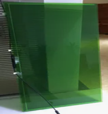 |
Option B | Size: 1200*600*7mm Transparency: 60% Nominal power = 42 W Open-circuit voltage = 122.5 V Short-circuit current = 0.49 A Voltage at maximum power = 89.7 V Current at maximum power = 0.42 A | 42 W | 4 | 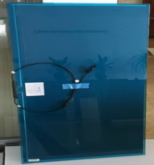 |
Using Table 5, therefore, the daily energy ($E_{\mathrm{daily}}$) estimate for CdTe option A (31 W) and B (42 W) was obtained as follows:
where, $E_{\mathrm{daily}}$ is the CdTe solar panel’s daily energy, $P_{\mathrm{m}}$ is the nominal max power of the panel, and $\text{PSH}$ is the peak sun hour.
For Option A:
\[ E_{\mathrm{daily}} = 4\left(31\ \text{W} \times 5.1\ \text{h} \times 0.75\right) = 0.4743\ \text{kWh/day} \]
For Option B:
\[ E_{\mathrm{daily}} = 4\left(42\ \text{W} \times 5.1\ \text{h} \times 0.75\right) = 0.6426\ \text{kWh/day} \]
Therefore, CdTe total contribution (Options A & B) is as follows:
\[ E_{\mathrm{daily}} = \left(0.4743 + 0.6426\right)\ \text{kWh/day} = 1.12\ \text{kWh/day} \]
The equivalent nominal peak power capacity of the CdTe photovoltaic system, expressed in kilowatt-peak (kWp), required to generate the same daily electrical energy under the specified peak sun hour conditions and the assumed photovoltaic derating factor, was determined using Eq. (36).
$$\mathrm{CdTe}_{\mathrm{equiv}}=\frac{1.12}{5.1\times 0.75} =0.3\ \mathrm{kWp}$$
Using Eq. (34) and considering safety margins, the estimated photovoltaic to meet the daily electrical demand was 670 Wp of photovoltaic array, then the extra photovoltaic ($PV_{\mathrm{Extra}}$) required to meet the demand was obtained as follows:
$$ \mathrm{PV}_{\mathrm{Extra}} = 0.67-0.3\ \mathrm{kWp} = 0.27\ \mathrm{kWp} $$
The study's greenhouse roof was equipped with four CdTe solar panels, of 70% transparency (green) each, generating 31 W, along with four additional CdTe panels of 60% transparency (Blue) each, generating 41 W, as illustrated in Figure 1 and Figure 2. However, this setup was insufficient to meet the system’s total energy demand. Therefore, to bridge the gap, crystalline solar panels were added and installed 5 meters from the greenhouse to fulfill the extra photovoltaic needs.
The common nameplate rating for crystalline panel wattage is 150–200 W (small 12 V module), 250 -330 W (legacy 60-cell), and 400–550 W (modern 54/60/72-cell) [53]. A 400 W panel was used for the study. The system's extra photovoltaic demand was 0.27 kW/270 W. The crystalline panel count was determined by dividing the required peak power extra demand by the selected panel’s nameplate wattage, as shown in Eq. (38) [54].
\[ N = \left\lceil \frac{270}{400} \right\rceil = 0.675 = 1 \text{ panel of 400 W} \]
Therefore, if CdTe panels were used as side walls instead of polycarbonate sheets, the equivalent CdTe solar panels that would meet the same system load were obtained using Eq. (38).
\[ \text{For the 70% CdTe} = \left\lceil \frac{270}{31} \right\rceil = 9 \text{ panels} \]
\[ \text{For the 60% CdTe} = \left\lceil \frac{270}{41} \right\rceil = 7 \text{ panels} \]
Assume a photovoltaic array's maximum power is $\text{PV}_{\mathrm{max}} = 0.67$ kWp ($\text{PV}_{\mathrm{conservative}}$), and the battery nominal is 24 V. The maximum power point tracking charge current ($I_{\mathrm{pv}}$) was estimated as follows:
where, $V_{\mathrm{sys}}$ is the system voltage.
\[ I_{\mathrm{pv}} = \frac{670}{24} = 28 \text{ A} \]
After adding 40% safety margin to cater for short-term peaks and future expansion, a maximum power point tracking charge controller rated at 50 A and 24 V was selected.
Based on the system’s peak instantaneous load and earlier loads from pumps, humidifier, controllers, and light-emitting diode grow lights, an inverter with a continuous rating that is greater than or equal to the expected alternating current load and surge rating for motor starts was required. Therefore, from the above analysis and the recommendations of Walker and Desai [52], a 24 V, 1500 W pure sine with a surge rating of 3000 W inverter was selected.
To analyze fluid problems and their behavior, CFD uses numerical methods. It predicts the interaction between liquids and gases, thus speeding up the design process and making product development more cost-effective than traditional testing methods [55]. For this study, therefore, the flow pattern and temperature distribution were predicted using CFD.
SolidWorks Flow Simulation employs the Navier-Stokes equations in the fluid region, which express the fundamental conservation laws using Eqs. (40) to (44) of mass, momentum, and energy [56].
In the analysis of high-speed compressible flows and flows characterized by shock waves, the following energy equation is employed [56].
From the study by Zhang et al. [55], in solid regions, SolidWorks Flow Simulation calculates two physical phenomena, i.e., direct electric current and heat conduction. Heat transfer in fluids and solids with energy exchange (conjugate heat transfer) is an implicit and necessary component of computer-aided design embedded in the CFD package of the software.
The electric current density vector is obtained as follows:
And it is determined using the electric potential $\varphi$ [V] from the steady-state Laplace as follows:
For high-quality tomato growing in a greenhouse, maintaining optimal indoor crop growing conditions is essential. Therefore, CFD can be applied to analyze airflow pattern and thermal behavior under three conditions, that is, natural, forced, and hybrid ventilation. For this study, the aim was to identify the best condition (configuration) for the physical implementation. The DoE approach was applied to the most promising design from the simulations, thoroughly varying operational parameters to assess their influence on the greenhouse performance. The goal was to determine the most efficient ventilation design configuration (Figure 3, Figure 4, and Figure 5) for tomato cultivation. To achieve that, the sized greenhouse system parameters and the tomato crop optimal growth conditions (Table 6) were used.
Description | Parameter |
|---|---|
Greenhouse geometry (gable type) | Length = 3.60 m, width = 2.253 m, height = 2.0 m, roof pitch = 20° |
Roof grazing (thin-film CdTe) | overall heat transfer coefficient (U-value) = 2.5 W/m$^2$·K |
Polycarbonate sheet (side wall glazing) | U-value = 5.0 W/m$^2$·K (single high-density polyethylene film) |
Site coordinates | 0.46°N, 34.1° |
RH | 50-60% |
ACH | 40 ACH |
Air flow fan capacity (air flow) | 573 cubic feet per minute |
Volumetric flow rate by natural ventilation at each vent | 0.203 m$^3$/s |
Each fan’s volumetric flow rate (Sanyo Denki) | 0.180 m$^3$/s |
Greenhouse indoor temperature | 25 $^{\circ}\mathrm{C}$ |
Supply air temperature | 30–40 $^{\circ}\mathrm{C}$ maximum |
Coldest supply temperature | 16 $^{\circ}\mathrm{C}$ |
Hot air volumetric flow@40 $^{\circ}\mathrm{C}$ to maintain 25 $^{\circ}\mathrm{C}$ from the coldest temp of the greenhouse (16 $^{\circ}\mathrm{C}$ for Busia district) | 0.0666 m$^3$/s |
Boundary conditions are crucial for establishing the inlets and outlets governing fluid dynamics. Therefore, the computed parameters (Table 6), together with the known values, including the volume flow rates for each fan, the volumetric flow rates associated with natural ventilation at each vent, and the volumetric flow of heated (hot supply air) air at 40 $^{\circ}\mathrm{C}$, which were necessary to sustain an internal greenhouse temperature of 25 $^{\circ}\mathrm{C}$ under the most extreme conditions (16 $^{\circ}\mathrm{C}$, the recorded minimum for the Busia district) were incorporated in this investigation. Hence, this analysis focused on the airflow pattern, temperature distribution, and the overall velocity profiles within the greenhouse environment. It is important to note that this study simulated the system using the coldest recorded temperature in the Busia district, particularly 16 $^{\circ}\mathrm{C}$, as the external ambient temperature for the greenhouse, a hot air supply flow of 40 $^{\circ}\mathrm{C}$ from the heater to raise the internal temperature from 16 $^{\circ}\mathrm{C}$ to the optimal level for tomato growth. The CFD analysis conducted was an internal flow, using a single-layer polycarbonate sheet as the glazing material and CdTe and clear polycarbonate as the roof.
The CFD simulation goals (Table 7) were used to evaluate the thermal, aerodynamic, and energy flow dynamics of the greenhouse under different ventilation conditions [57]. These included global goals that focused on the overall greenhouse thermal effectiveness, namely, the average and maximum temperatures and mass flow rates, allowing for a comparison of natural, forced, and hybrid ventilation. Surface plot and point plot objectives were set at canopy height (tomato crop) and the center of the greenhouse, providing a comprehensive assessment of the energy optimization performance and enabling design configuration comparisons.
| Goal Type | Goal Bame | Measured Variable (s) | Location/Boundary | Purpose/Justification |
|---|---|---|---|---|
| Global goal | Air temperature | Average and maximum air temperature | Entire greenhouse domain | Evaluate thermal performance, overheating, and comfort levels for tomato production |
| Global goal | Total mass flow rate | Mass flow (kg/s) | Inlet/outlet vents | Compare the efficiency of natural, forced, and hybrid ventilation designs. |
| Surface goal | Vent flow velocity | Velocity (m/s) | Side vents | Evaluate natural ventilation effectiveness. |
| Surface goal | Canopy heat transfer | $h$ (W/m$^2$·K), local heat flux | Tomato canopy surface | Quantify convective exchange between plants and greenhouse air. |
| Point goal | Canopy sensor point | Temperature and velocity | 1.2 m above floor (plant height zone) | Compare CFD predictions |
| Point goal | Central sensor | Temperature and velocity | Center of the greenhouse | Monitor mid-air microclimate stability |
The greenhouse envelope and CdTe solar Panel layout were modeled in SolidWorks 2024 and exported to the flow simulation add-in. The locally refined tetrahedral meshes ($\leq$5 mm) were created around the side and roof vents and panel edges to capture steep velocity and temperature gradients.
Flow-trajectory analysis was conducted to visualize and quantify the airflow patterns within the CdTe greenhouse under the three modes of ventilation scenarios. The computational domain was defined to include the greenhouse enclosure, vents, and fan locations. Streamlines were generated to illustrate the direction, velocity, and distribution of airflow. To enable the identification of recirculation zones, i.e., the inlet–outlet pathways and canopy-level mixing, the trajectories were computed at one-minute intervals and averaged to highlight stable flow structures.
Orthogonal planes were defined, and temperature fields were extracted. Cut‑plots were to help provide quantitative temperature gradients across the greenhouse so that the comparison of different vent configurations could be conducted.
To visualize regions of equal scalar values, particularly temperature and velocity fields, inside the CdTe greenhouse, isosurface plots were generated. In order to identify zones with uniform microclimatic conditions, the plots provided three‑dimensional representations of thermal stratification and airflow distribution, enabling the identification of zones with uniform microclimatic conditions.
Numerical simulations were performed using the Favré averaged Navier-stokes equations implemented in SolidWorks flow simulation. To accurately model the thermal plumes and airflow inside a CdTe greenhouse, the following settings were applied in the study.
$\bullet$ A modified $k-\epsilon$ turbulence model (often referred to as a low-Reynolds number model) with a damping function was employed. The model captures the transition from laminar to turbulent flow in buoyant-driven internal environments like greenhouses [58].
$\bullet$ For the wall functionality, enhanced wall treatment was used to resolve the boundary layer effects near the CdTe photovoltaic glazing and polycarbonate glazing surfaces, which is critical for calculating accurate convective heat transfer.
$\bullet$ For solver controls, a steady-state pressure-based solver was used in this study. To ensure high spatial accuracy, a second-order upwind scheme was used for momentum and energy for the discretization of the governing equations.
$\bullet$ The conditions for the convergence criteria were met when the residuals for mass, momentum, and energy dropped below a small number, specifically 10$^{-5}$, which was also consistent with the approaches proposed by Chen et al. [59] and Dairi et al. [60]. Additionally, the global goals (average canopy surface temperature and the total mass flow rate) were monitored constantly to make sure that they remained stable with fluctuations $<$ 0.1% for at least 100 iterations.
A mesh independence test was conducted to ensure that the results were independent of the grid density using three different mesh levels: coarse, medium (base), and fine [61]. Therefore, this study used the average canopy temperature as the primary sensitivity parameter. Since the medium mesh provided a well-balanced computational efficiency and numerical accuracy, with the relative error falling well below the 1% threshold as compared to the fine mesh, it was selected for all subsequent simulations.
The DoE in the SolidWorks Flow Simulation was used to evaluate the combined effects of ventilation geometry and the fan’s volumetric flow on the coldest day of 16 $^{\circ}\mathrm{C}$ outside ambient temperature and supply air of 40 $^{\circ}\mathrm{C}$ from the heater source to maintain the indoor temperature in the required range of 20–25 $^{\circ}\mathrm{C}$. The upper vent was kept at atmospheric pressure. Independent variables included side-vent size, inlet and exhaust-fan volumetric flow rates, and hot-supply air volumetric flow rate and temperature. The dependent variables or quantities of interest were spatial temperature uniformity, average canopy temperature, and wind speed at plant height (1.2 m above the greenhouse floor).
The global goals of interest included maximum and average temperatures inside the greenhouse, and the velocity of air at 1.2 m height from the greenhouse floor. The Taguchi fractional factorial design was adopted in the study to reduce the number of simulations to a manageable level while preserving important interactions [62], [63], [64]. Twelve experiments were run, and the resulting response surfaces and cut plots were determined. The optimal design parameters for greenhouse comfort and energy efficiency of the hybrid convective greenhouse were established. Table 8 is the baseline or operating point used in the DoE.
| Component | Quantity | Flow Rate (m$^3$/s per unit) | Total Flow (m$^3$/s) |
|---|---|---|---|
| Side vents | 2 | 0.203 | 0.406 (fixed) |
| Inlet fans | 4 | 0.18 | 0.72 |
| Exhaust fans | 4 | 0.18 | 0.72 |
| Upper vent | 1 | Atmospheric pressure | Passive |
| Hot air supply | 1 | 0.0666 | 0.0666 at 40 $^{\circ}\mathrm{C}$ |
Level | Parameter Description | Rationale | ||
Inlet fan flow rate | Flow rate (m3/s per fan) | Total inlet flow (4 fans) | 0.09m3/s represents minimum effective mechanical ventilation, and 0.27 m3/s represents aggressive ventilation without excessive turbulence. | |
Low | 0.09 | 0.36 | ||
Center | 0.18 | 0.72 | ||
High | 0.27 | 1.08 | ||
Exhaust fan flow rate | Flow rate (m3/s per fan) | Total exhaust flow (4 fans) | Allows the evaluation of imbalanced scenarios Maintains pressure stability | |
Low | 0.09 | 0.36 | ||
Center | 0.18 | 0.72 | ||
High | 0.27 | 1.08 | ||
Hot air supply flow rate | Low | 0.0333 | 0.0333 | 0.040 m3/s is the minimal heating scenario. 0.090 m3/s is the upper limit before the jet dominance and the hot spots occur. |
Center | 0.0666 | 0.0666 | ||
High | 0.1 | 0.1 | ||
Temperature of supply air | Low | 25℃ | 25 ℃ | The lowest temperature used was 5℃ above the room temperature. |
Center | 40℃ | 40 ℃ | ||
High | 75℃ | 75 ℃ | ||
The DoE analysis requires two values, which are the minimum and maximum of the baseline values for simulation. Therefore, the inlet, exhaust, and hot air supply flow rates and temperature were varied to $\pm$ 50% of the nominal design values or baseline (center-value) [65] except for the supply temperature to capture nonlinear thermal and airflow behavior while maintaining realistic greenhouse operating conditions. It should be noted that if too low or too high inlet or exhaust flow is used, it might cause heat stratification and poor carbon dioxide distribution, overcooling, and energy waste [66], [67]. And if an air supply is used that is too cold or too hot, it may cause the system to fail to reach the required indoor temperature of 25 $^{\circ}\mathrm{C}$ on the coldest day, as well as create local hot spots and plant stress. It should be noted that the side vents and upper vent remained constant at atmospheric pressure, respectively, to isolate mechanical effects. Therefore, Table 9 is the DoE factors and ranges used for the 12 experiments.
Twelve experiments were conducted in SolidWorks Flow Simulation under the DoE and optimization, where the input variables were data from Table 9. The output parameters under the global goals included the maximum, minimum, and average temperature of the air inside the greenhouse. The global surface goals included the minimum, maximum, and average temperature of the air inside the greenhouse, and the average surface area of the plant canopy. The objective was to optimize the thermal environment inside the combined (hybrid) greenhouse for tomato production, focusing on two key indicators, i.e., average indoor air temperature and average surface temperature of the plant canopy.
To validate the CFD model predictions, a physical smart integrated CdTe greenhouse was constructed at the study site in Busitema University.
A prototype with a length of 3.60 m, width of 2.253 m, height of 2.0 m, and roof pitch angle of 20°, matching the CFD geometry specifications, was constructed at Busitema University. The prototype (Figure 6) consists of a full-size CdTe roof glazing of both 60 and 70% transparency, and 100% clear glass as control, polycarbonate sheet side walls and gable ends, and functional automated systems (natural and mechanical ventilation, pneumatic, heating, irrigation, full-spectrum light-emitting diode glow lights, and humidification).
The system was equipped with an extensive array of instrumentation and control sensors and actuators set to monitor and measure both internal microclimate and external ambient conditions through the use of the Internet of Things technology, Davis weather stations, Type-K thermocouples, and more. This setup (Figure 7) and their network architecture (Table 10) were detailed in the five-layer system structure.
| No. | Layer | Description | Function |
|---|---|---|---|
| 1 | Sensing layer | Davis Vantage Pro2 weather station and internal greenhouse sensors (temperature, RH, soil moisture, carbon dioxide) | Collect real-time environmental data |
| 2 | Data aggregation layer | Weather console, WeatherLink interface, and computer | For data logging, visualization, and raw data storage |
| 3 | Communication layer | Weather console, Modbus gateway (RTU/TCP), programmable logic controller, and ESP32 controller | For communication protocols |
| 4 | Control layer (decision making) | Programmable logic controller, ESP32 controller, control inputs (solar irradiance, temperature, humidity, and soil moisture) | For controlling ventilation, irrigation, climate control, pneumatic systems, and humidification |
| 5 | Actuation layer | Actuated by an ESP32 output signal through relays | Ventilation system (inlet and exhaust fans), pneumatic system (solenoid valves, air compressor, cylinders for vent opening), irrigation system (water pump and valves), lighting system (full-spectrum light-emitting diode grow lights), humidification system (ultrasonic humidifier) |
To characterize the microclimate within the CdTe greenhouse, a set of sensors was installed to capture temperature, humidity, and airflow dynamics. The type-K thermocouples ($\pm$0.5 $^{\circ}\mathrm{C}$ accuracy) and resistance temperature detector sensors ($\pm$0.2 $^{\circ}\mathrm{C}$ accuracy) were installed at 15 points distributed across three vertical levels. This arrangement allowed us to assess the vertical temperature gradients.
$\bullet$ Level 1 (0.5 m height), five sensors were positioned near the soil air interface.
$\bullet$ Level 2 (1.5 m height), sensors were positioned within the crop canopy zone.
$\bullet$ Level 3 (3.0 m height) contained five sensors to monitor the upper air layer.
A Davis weather console was placed centrally at 1.2 m above the greenhouse floor to provide reference measurements. For horizontal distribution, the greenhouse was partitioned into a north–center–south $\times$ east–center–west grid, ensuring spatial coverage across the entire structure. The RH was monitored using DH22 and Vaisala HMP60 capacitive RH sensors, each with an accuracy of $\pm$3%. Six sensors were positioned at crop canopy height (1.5 m) to capture humidity variations within the zone most relevant to plant physiology.
The airflow velocity was measured using hot-wire anemometers (TSI Model 8465), which provided an accuracy of $\pm$0.02 m/s for velocities greater than 0.1 m/s. Eight measurement points were selected to capture both inlet and exhaust flows as well as internal circulation. Finally, a Davis meteorological station was installed above the greenhouse to provide boundary conditions for CFD simulations. The station measured ambient temperature, RH, solar radiation (via pyranometer), wind speed and direction, and atmospheric pressure. These external parameters were essential for contextualizing the internal microclimate data and for validating simulation outputs against observed environmental conditions.
To validate the different ventilation modes (natural, mechanical, and hybrid ventilation), data for each scenario was collected for 48 L on different days, such as January 10$^{\text{th}}$–12$^{\text{th}}$ 2026 for natural ventilation, January 18$^{\text{th}}$–20$^{\text{th}}$ 2026 for mechanical ventilation, and January 25$^{\text{th}}$–27$^{\text{th}}$ 2026 for hybrid ventilation.
For each test period of this study, steady-state conditions were identified for the periods when the temperature and solar radiation varied by $<$2 $^{\circ}\mathrm{C}$, and $<$50 W/m$^2$ over one hour [68]. With boundary conditions matching the averaged ambient conditions during these steady periods, CFD simulations were run.
To access the agreement between the experimental measurements and the CFD predictions, five standard statistical metrics were computed, as shown in Eq. (49) (Coefficient of Determination, $R^2$), Eq. (51) (Root Mean Square Error, RMSE), Eq. (50) (Mean Absolute Error, MAE), Eq. (52) (Mean Bias Error, MBE), and Eq. (53) (Normalized Mean Bias Error, NMBE).
where, $O_i$ is the observed value, $P_i$ is the predicted (simulated) value, $\bar{O}$ is the mean of observed values, and $n$ is the number of data points.
3. Results and Discussion
This section presents the results from the CFD simulations, parametric optimization studies, and the CFD model validation against experimental data.
The flow trajectories of the three configurations revealed different airflow behaviors influenced by buoyancy and mechanical moments. It’s evident (Figure 8) that the flow rate is determined by the buoyancy force, which is caused by the temperature gradient from the greenhouse’s internal heat source. Hot air rose vertically from the radiator, creating strong hot smoke that spread all the way to the roof. It was also observed that the upward movement was restricted in terms of horizontal diffusion, and the heated air stratified along the greenhouse roof, forming a high-temperature zone and a low-velocity layer consistent with the Rayleigh-Bénard convection model. This stratification behavior is thermodynamically predictable. As the Archimede number (the ratio of buoyancy to inertial forces) increases under low velocity natural flow conditions, the gravitational stability of the warm upper layer strengthens, effectively suppressing vertical mixing and anchoring the thermal boundary at the roof level [69]. It was also observed (Figure 8) that the weak downward flow circulation failed to disrupt the thermal stratification, which then resulted in short and unsteady (transient) flow paths near the tomato vegetation canopy. However, this uneven temperature/thermal distribution led to heat accumulation near the roof and upper vent and the formation of cold pockets at the plant level, thereby reducing convective heat transfer to the microclimate. These cold pockets at the canopy level have a practical agronomic consequence that is significant. The localized sub-optimal temperatures suppress stomatal conductance and reduce the rate of photosynthetically active radiation utilization in tomatoes, particularly during early morning and late afternoon periods when the internal to external temperature differentials is smallest [70]. In general, the natural ventilation had relatively low mixing efficiency and was strongly influenced by the greenhouse dimension constraints, vent location, and the internal heat load.
The forced ventilation model (Figure 9) revealed that the mechanical fans impart strong directional momentum, considerably altering the airflow behavior. The flow trajectories became well-defined and aligned with the fan orientation, leading to higher air velocity, improved circulation, and better warm-air distribution in the greenhouse. This behavior is similar to the findings of Walker and Desai [52], who demonstrated that thermal destratification can be achieved through the installation of appropriate ventilation equipment, such as bucket fans below the ceiling. It helped break the stratification and effectively reduced the temperature gradients. It was observed that the mechanical mixing by the fans disrupted the vertical heat plume, which promoted lateral heat redistribution, induced turbulence within the crop canopy, and also reduced temperature stratification. This disruption of the vertical heat plume, as reported by Norton et al. [71], is mechanically explained by the fan’s ability to increase the bulk Reynolds number of the airflow beyond the transitional threshold, which shifts the internal flow regime from the laminar dominated stratification toward turbulent mixing which is a transition that fundamentally alters the heat and mass transfer coefficients at the canopy boundary layer. This resulted in more uniform treatment, reduced stagnation zones, and allowed the heated air to flow downwards, which improved the greenhouse microclimate and heat distribution to the crop. However, according to Bhandari et al. [72], excessive fan speeds can cause drafts and excessive ventilation in cold environments if not properly controlled. This limitation is particularly relevant in the Busitema University site context, where nighttime temperatures can drop sharply during the dry season, meaning that the unregulated fan operation could accidentally push internal temperatures below the 16 $^{\circ}\mathrm{C}$ threshold that inhibits tomato fruit set [73]. This supports the case for the smart Internet of Things controlled ventilation actuation integrated 73 into the greenhouse prototype, rather than fixed-speed mechanical operation. In general, the forced ventilation model showed stronger mixing and consistent flow paths as compared to the natural ventilation model, highlighting the relevance of mechanical ventilation for microclimate uniformity.
The hybrid ventilation system (Figure 10) combines buoyancy and mechanical drivers to create efficient airflow. The mechanical fans and side vents facilitated horizontal transport and canopy-level mixing, while the upper vent allowed hot air to escape. This resulted in a dual-driven circulation pattern, i.e., forced-flow pathways from the inlet fans and side vents, and natural-convective plumes rising to the roof vent. This integration stabilized the airflow, preventing hot air zones and hot air accumulation, thus minimizing recirculation and dead zones. In the CdTe glazed greenhouse, the elimination of dead zones is consequential, where the semi-transparent panels absorb a portion of incident solar radiation and re-emit it as longwave radiation to the greenhouse interior, a localized radiative loading effect that, without active airflow disruption, would intensify stagnation zones and create hotspot temperatures exceeding the crop tolerance thresholds [74]. The flow distribution from the hybrid model was less turbulent than in forced ventilation and more uniform than in natural ventilation, leading to optimal thermal mixing efficiency, effective heat distribution, and a more controlled hot air removal, making it the most energy-efficient option for the proposed greenhouse. From the energy balance perspective, the hybrid system’s advantage lies in its ability to achieve a ventilation rate at lower fan duty cycles than the forced ventilation, since the buoyancy component supplements the mechanical pressure gradients, thereby reducing the vampire load (parasitic electrical consumption), and thus improving the overall energy self-sufficiency ratio of the photovoltaic-integrated systems.
A comparison of the three models showed clear differences, where in natural ventilation, the air moves mainly upward due to warm air rising, which creates high thermal stratification and limits the mixing of air. For forced Ventilation, air flow is greatly influenced by fans, which leads to better mixing, a more even spread of air, and less thermal stratification. For the hybrid ventilation, the model combines natural rising air with fan-driven mixing, which results in the best thermal distribution and steady airflow pattern. These differences show that using both natural and mechanical ventilation together can control the internal microclimate much better, leading to improved thermal comfort of the greenhouse and creating an optimal microclimate for tomato growing. Importantly, these findings align with and extend the conclusion of Bournet and Boulard [69], who established the theoretical superiority of hybrid ventilation strategies in controlled-environment agriculture. However, the present study advances this understanding by experimentally validating these strategies for the first time within a semi-transparent CdTe photovoltaic greenhouse operating under equatorial tropical climatic conditions. Under such conditions, the greenhouse glazing material performs a dual function as both an ultraviolet radiation filter and a radiative heat source, thereby generating a uniquely complex internal thermal environment that has not been adequately addressed in previous studies conducted under temperate climatic conditions. Consequently, the present study represents a substantial original contribution to the field of greenhouse environmental control and photovoltaic-integrated protected agriculture.
This section outlines the temperature fields for three types of greenhouse models, that is to say, natural ventilation, forced ventilation, and hybrid (which combines both natural and forced ventilation). The effect on heat distribution, temperature stability, and climate uniformity within the greenhouse was demonstrated from the results and findings of the study. Therefore, understanding these effects is essential to increasing heating efficiency and creating optimal growth conditions. The plot temperature distribution fields complement the earlier Section 3.1.1 about the flow trajectory by providing spatially resolved quantitative evidence of the thermal consequences of each ventilation strategy, allowing a direct assessment of their agronomical suitability for tomato production under the equatorial conditions of the Busitema University installation site.
(a) Natural Ventilation Cut Plot
Natural ventilation temperature field (Figure 11) showed the most uneven heat distribution among the three models simulated. The heat source created a buoyant plume that ascended rapidly to the roof near the upper vent, reaching temperatures of up to 40.01 $^{\circ}\mathrm{C}$, the highest recorded in this research. The warm air accumulated near the greenhouse ceiling and close to the upper vent, forming a stable layer that was mainly influenced by buoyancy. Unlike forced or hybrid systems, the warm air in the natural ventilation didn’t spread well throughout the greenhouse. The heat stayed concentrated around the heater inlet duct to the greenhouse, and near the roof, leaving the lower part of the greenhouse, especially around the crop canopy, much cooler, between 15.76 $^{\circ}\mathrm{C}$ and 17 $^{\circ}\mathrm{C}$. This temperature range at the canopy falls below the critical minimum of 18 $^{\circ}\mathrm{C}$ that is required for sustained tomato vegetative fruit growth and development. The sustained exposure to the sub-optimal temperatures at this level is known to impair cell division in developing fruit tissues, reduce pollen viability, and slow the rate of dry matter accumulation. The outcome directly translates into reduced marketable yield [75]. The low temperatures indicate that there is not enough movement of air inside the greenhouse to carry heat to the planting area. Therefore, the temperature difference of more than 20 $^{\circ}\mathrm{C}$ between the roof and the ground illustrated the limitations of natural ventilation for heating the greenhouse. This vertical temperature gradient, which is greater than 20 $^{\circ}\mathrm{C}$ is significantly larger than the maximum 5–8 $^{\circ}\mathrm{C}$, which is the differential typically tolerated in commercial greenhouse tomato production without significant crop stress. This is also thermodynamically explained by the dominance of the Archimedes number over the Richardson criterion for stratification onset, a condition that, once established, becomes self-reinforcing because of the stable density gradient that actively resists the vertical momentum needed to break it [76]. This strong and constant thermal stratification leads to energy loss and waste. This is because most of the heat accumulates in the upper part of the greenhouse, near the roof or ceiling, where it is least helpful for growing crops. This shows that natural ventilation alone is not sufficient to ensure a uniform temperature distribution during cold weather.
(b) Forced Ventilation Cut Plot
A strong horizontal flow of warm air starting from the heated air inlet (Figure 12) was indicated by the forced ventilation temperature plume. The highest temperature recorded was 38.5 $^{\circ}\mathrm{C}$, occurring in the heated air stream just a few millimeters from the heat source, where a mechanical fan blows hot air. A long temperature plume was observed, and it was well-oriented, which indicates that the airflow from the fan is stronger than the natural upward temperature plume. This dominance of the mechanically driven horizontal plume over the buoyant vertical plume is consistent with a low Archimedes number regime, where inertial forces largely exceed buoyancy forces, effectively suppressing thermal stratification in the longitudinal direction while leaving the transverse corners relatively unaffected by the primary jet [71]. The forced circulation system created a constant layer of warm air that moved throughout the greenhouse, and ultimately cooled down to about 24–25 $^{\circ}\mathrm{C}$. However, it was also noticed that the temperatures in the upper right and lower right corners remained much cooler, i.e., 17.85 to 18.0 $^{\circ}\mathrm{C}$, respectively. This shows that those corners received less heat from above the greenhouse, and therefore, while forced ventilation quickly warms the air in the greenhouse, it DoEs not fully mix the air vertically with an additional airflow. According to Mistriotis et al. [77], the persistent corner cold zones are a characteristic consequence of the wall-jet separation phenomenon, in which the primary airstream detaches from the boundary layer at sharp geometric discontinuities. An example is the wall-to-roof junction that fails to reattach sufficiently to deliver thermal energy to recirculation-dominated corner regions. In the CdTe-glazed greenhouses specifically, this effect may be increased during the peak solar hours, especially during the midday period, as the panels’ longwave re-emission creates an additional thermal load at the roof periphery that reinforces the corner temperature deficit. From the observed pattern, it can be concluded that although forced ventilation increases the speed and efficiency with which heat reaches the crops, some areas may remain cold without vertical airflow. In general, compared to natural ventilation, forcing systems considerably improve heat transfer to the mid-height growing zone and reduce the size of cold spots.
(c) Hybrid Cut Plot (Combined Natural and Forced Ventilation)
The results from the hybrid ventilation model (Figure 13) showed a different temperature pattern compared to the forced ventilation. The highest temperature recorded is 39.98 $^{\circ}\mathrm{C}$, occurring right at the heat source exit. However, the pattern of the heat/temperature plume differs markedly. As the heated air moved throughout the greenhouse, it rose due to the buoyancy force, thus creating a larger and more evenly distributed warm air pattern. The simultaneous operation of the buoyancy-driven vertical plume and the fan-driven horizontal regime generate a compound circulation regime in which each mechanism compensates for the other’s geometric limitations. The vertical buoyant flow delivers thermal energy to the roof periphery and corner regions that the horizontal jet DoEs not reach, while the mechanical jet disrupts the stable upper stratification layer that buoyancy alone reinforces. This interdependent interaction forms the fundamental thermodynamic basis for the hybrid system’s enhanced uniformity [78]. This hybrid ventilation model decreased the number of cold spots. It was noticed that the lowest temperature reached 16.82 $^{\circ}\mathrm{C}$. The cold area in the combined model was smaller and more focused than those in the forced ventilation model. The side vents, the fan, and the open upper vent aided in air circulation; therefore, the warm temperature plume rose higher, which led to a more unified temperature distribution throughout the greenhouse.
The hybrid system or hybrid ventilation/ventilation model demonstrated an improved thermal mixing as compared to both the natural and forced ventilation. The center or central part of the greenhouse structure achieved temperatures of between 19 $^{\circ}\mathrm{C}$ and 22 $^{\circ}\mathrm{C}$, providing a smoother and more consistent warmth than the purely forced ventilation model. This central temperature range of 19–22 $^{\circ}\mathrm{C}$ aligns closely with the optimal daytime growing range for tomatoes and is particularly significant for the money maker and Tengeru varieties investigated in this study, as both are known to exhibit maximum photosynthetic efficiency and fruit set rates within this thermal window under East African agroclimatic conditions [79]. The heat streams that rise to or towards the roof of the greenhouse help to reduce stagnation, while the fan disperses the warm air [80]. The integration of natural and forced ventilation results in a more balanced indoor microclimate for greenhouses, which demonstrates that hybrid/hybrid ventilation effectively integrates both vertical and horizontal heat movement. Furthermore, from the perspective of energy efficiency, the hybrid system’s capability to attain thermal uniformity at lower fan duty cycles, in comparison to the convectional forced ventilation, significantly reduce the parasitic electrical consumption (vampire load). This aspect particularly pertinent in the context of photovoltaic-integrated greenhouses, in which the equilibrium between energy generation and operational energy demands profoundly influence the overall net energy advantage of the system [81].
Comparing the three models, natural ventilation causes heat accumulation at the roof with minimal heat reaching the plants. This results in temperature differences of up to 20 $^{\circ}\mathrm{C}$ and energy losses, whereas forced ventilation effectively spreads heat horizontally but leaves cooler portions, and also has limited vertical mixing, which affects plant growth. The combined model balances the heat distribution and reduces temperature differences by creating a uniform environment. Overall, the hybrid ventilation model is the most effective, utilizing both mechanical and natural airflow advantages, thus maintaining a stable and energy-efficient greenhouse environment. These comparative findings are consistent with the findings of several studies [15], [69], which extend those conclusions into a novel context of a semi-transparent CdTe photovoltaic roofing system under tropical equatorial conditions, where the dual role of the glazing material as both spectral filter and radiative heat emitter introduces thermal dynamics not captured in prior temperature zone studies.
In forced ventilation (Figure 14), the heat distribution is smooth due to the airflow generated by the fans. The quick convergence is observed in iteration 71, which indicates that the system reached a steady state, mainly due to the mechanical forces created by the fans. This rapid convergence observed at iteration 71 has significant physical implications. The influence of mechanically imposed boundary conditions diminishes the solution's sensitivity to initial field estimates, thereby enabling the solver to identify the momentum balanced steady state with fewer iteration compared to buoyancy dominated configuration. In the latter case, the intricate coupling between the temperature and velocity filed necessitates a greater iterative effort for resolution [77]. However, this can result in cold spots or drafts [82], [83].
After 460 iterations, the temperatures in natural ventilation showed a notable layering that ranged from 15.8 $^{\circ}\mathrm{C}$ to 40 $^{\circ}\mathrm{C}$. The substantially higher iteration count required for natural ventilation convergence, that is to say 460 vs. 71 for the forced ventilation, reflects the non-linear coupling between the buoyancy-driven velocity field and the temperature distribution. As reported by Bournet and Boulard [69], small perturbations in the temperature field alter the density gradient, which then modifies the velocity field and in turn redistributes heat, requiring many more iterative cycles before a self-consistent solution is achieved. This reflects a slower approach to reaching a steady state and thus highlights potential temperature differences that could affect a crop’s health in the greenhouse. At iteration 189, the hybrid ventilation system (Figure 15) had a blend of forced and natural airflow, and this led to more complex temperature patterns. However, it was noted that for the hybrid ventilation system, distortion occurs, but its ventilation improves the mixing inside the greenhouse and reduces heat extremes, thus creating a more balanced heat environment for the greenhouse. However, forced ventilation (Figure 14) disperses heat quickly but requires energy for the fans, and the resulting airflow may stress the plants [84], [85].
On the other hand, natural ventilation (Figure 16) conserves energy but leads to very poor air circulation and a high humidity in the greenhouse. A hybrid ventilation system strikes a balance if low-speed fans are to enhance air mixing without drastically reducing the beneficial heat differences, such as warming the root zone [86]. Areas with closely packed temperature lines indicate high heat differences and, therefore, in the hybrid ventilation scenario, heat distribution can inform the placement of vents and fans. Adding airflow in these spots can enhance mixing.
The global air temperature goals revealed a wide range of average greenhouse indoor air temperatures across the 12 experiments conducted (Figure 17), ranging from 17.79 $^{\circ}\mathrm{C}$ in Experiment 1 to 24.25 $^{\circ}\mathrm{C}$ in Experiment 4. Experiments 4, 8, 9 and 11 show that they achieved an average air temperature within the optimal range of 21–27 $^{\circ}\mathrm{C}$, which is ideal for daytime tomato growth [87]. These scenarios had higher hot air supply temperatures and moderately high inlet fan flow rates, which suggests that thermal input combined with adequate ventilation is essential for maintaining optimal air conditions inside a greenhouse. This interaction between thermal input magnitude and ventilation rate reflects the fundamental trade-off in greenhouse climate management. Insufficient ventilation traps heat and creates stratification, while excessive ventilation dilutes the thermal input before it can be uniformly distributed, and the four successful experiments suggest that the optimal operating point lies at a moderate ventilation intensity that balances these competing effects, consistent with the ventilation-heating coupling principles established by Bot [88], and later formalized in greenhouse energy balance modeling. However, the global surface showed that canopy temperatures closely followed the indoor air temperature trends, confirming the intrinsic thermal linkage between ambient air and plant surfaces [89]. The strong monitoring of canopy surface temperature with indoor air temperature also validates the assumption embedded in the CFD model that the tomato canopy can be adequately represented as a passive thermal surface in the absence of active transpiration cooling, which is an assumption that holds under the controlled heating conditions of these experiments but should be revisited under high solar radiation loading conditions where latent heat flux from transpiration becomes a significant component of the canopy energy balance [90].
It was observed that the average canopy surface temperature (Figure 18) ranged from 18.04 $^{\circ}\mathrm{C}$ in Experiment 1 to 26.54 $^{\circ}\mathrm{C}$. Experiments 11, 9, 8, and 4 also produced surface temperatures within the optimum. Therefore, the indoor average temperature (Figure 17) and the plant canopy average surface temperature (Figure 18) illustrate the dynamic thermal behavior across the iterations. It was also observed that experiments with higher thermal input and balanced ventilation showed smoother temperature profiles and fewer fluctuations, indicting stable thermal stratification and effective heat distribution. Therefore, Experiment 4 emerged as the most thermally favorable scenario, with the highest average air temperature of 24.3 $^{\circ}\mathrm{C}$ and canopy surface temperature, both of which are within the optimal range. It also featured an inlet volume flow rate of 0.22 m$^3$/s for each fan, a hot air supply temperature of 66 $^{\circ}\mathrm{C}$ at 0.1 m$^3$/s, and an exhaust fan outlet volume flow rate of 0.17 m$^3$/s for each fan, demonstrating the importance of high thermal input and controlled airflow. The parameters chosen from Experiment 4 form a solid foundation for the design of the physical prototype, and therefore, the configuration achieves not only the target thermal environment but also the DoE through a combination of moderate fan flow rates and elevated supply temperature that minimizes mechanical energy consumption, which is an important consideration given that parasitic fan energy directly reduces the net energy benefit of the photovoltaic-integrated system. It is also important to note that the 66 $^{\circ}\mathrm{C}$ supply temperature is achievable through resistance heating powered directly by the CdTe panel output, further reinforcing the energy self-sufficiency design logic of the integrated greenhouse.
The sizing and CFD analysis of the CdTe gable greenhouse integrated design revealed critical insights into thermal, ventilation, and irrigation performance of the system under Uganda climatic conditions. The CFD results demonstrated that the hybrid ventilation, that is, combining both natural and forced ventilation, offered superior control over internal microclimate parameters compared to standalone systems. As seen from the study, the case scenarios with open roof and open side vents reduced thermal stratification and led to a more uniform temperature distribution, and were very similar to what Flores-Velazquez et al. [15] and Mistriotis et al. [77] stated in their studies, which outline the benefits of buoyancy-driven airflow in greenhouse environments.
The greenhouse’s mechanical ventilation was designed to deliver 40 ACH, which translates to an airflow rate of 0.180 m$^3$/s and a fan power of 13 W, which was achieved by using four inlet and exhaust low-wattage fans, each having a flow rate of 0.180 m$^3$/s, ensuring energy efficiency while maintaining adequate air exchange. The natural ventilation sizing was based on 10% of the total floor area of the greenhouse, which yielded both the upper and side vent dimensions that supported an air volumetric floor rate of 0.203 m$^3$/s per side vent under typical conditions of 2 m/s air speed, and was consistent with the guideline of Awbi [26] for passive ventilation design, and yet the upper vent was designed to exhaust air out of the greenhouse at atmospheric pressure. The thermal analysis indicated that the heat loss of the system through conduction and infiltration varied considerably with external temperature outside the greenhouse. The system heat capacity was obtained using the coldest recorded ambient temperature of the installation site, which was 16 $^{\circ}\mathrm{C}$; therefore, the total heating requirement was 288 W, and with a 30% design margin, 0.5 kW heating power was recommended for the system to ensure resilience against infiltration peaks and dust losses, as emphasized by Vadiee [5]. The 30% design margin applied in this study is a standard engineering safety factor in building energy systems, but is particularly justified in the present context, given the variability of nighttime temperatures at the Busitema University site and the potential for dust accumulation on the CdTe panels to reduce power output below the nominal rated values, both of which would reduce available heating capacity and make the thermal buffer margin operationally critical.
Humidity control was another critical factor whose system required designing and sizing. Therefore, to maintain the required optimal RH of 75% during daytime ventilation, the system required a humidifier capacity of at least 5 L per hour, and this matched well with the findings of Schnelle et al. [39] that the humidifier nozzle placement should be elevated at least at a height of 1.6 m above floor level to prevent leaf wetting and ensure uniform vapor distribution. For the system’s irrigation, this was designed to handle a plant density of 3 plants/m$^2$, which required 44 L/day of water and was delivered in six pulses per day during the daytime to match the evapotranspiration rates and minimize runoff, and therefore, this agreed well with the recommendation of Schnelle et al. [39].
The pulse irrigation strategy adopted for this study is a six daytime pulses matched to evapotranspiration rates which is agronomically superior to continuous drip delivery in a controlled greenhouse environment because it prevents waterlogging of the root zone, maintains soil oxygen levels critical for nutrient uptake, and reduces the risk of fungal disease proliferation that is elevated under the persistently humid conditions of a semi-enclosed tropical greenhouse [33]. The alignment of irrigation timing with peak evapotranspiration hours also ensures that water application efficiency is maximized, minimizing the fraction of applied water lost to surface evaporation before root uptake, and a water use efficiency consideration of direct relevance to smallholder farmers for whom water scarcity is a recurrent operational constraint.
To establish confidence in the simulation results, this study validated the CFD model against experimental mean temperature measurements collected at three levels, as illustrated in Section 2.9.3, using the full-scale CdTe greenhouse prototype fabricated and installed at Busitema University (Figure 6 and Figure 19).
Experimental real-time data were obtained from the WeatherLink integrated with the system, as shown in Figure 7 and discussed in Section 2.9.2. Each experiment took 48 hours, and the WeatherLink captured data every 2 hours on average. Validation was performed using five standard statistical metrics, as shown in Eqs. (49) to (53), calculated at the sensor locations and time points where both experimental observations ($O_i$) and CFD predictions ($P_i$) were available ($n$ = number of paired points). Table 11 shows the overall CFD validation metrics for all configurations (natural, mechanical, and hybrid ventilation) and Figure 20 shows the scatter plots of the measured versus the simulated temperature for the three ventilation systems.
Ventilation | Paired Points (n) | R2 | RMSE ($\boldsymbol{^{\circ}\mathrm{C}}$) | MAE ($\boldsymbol{^{\circ}\mathrm{C}}$) | MBE ($\boldsymbol{^{\circ}\mathrm{C}}$) | NMBE (%) | Interpretation |
|---|---|---|---|---|---|---|---|
Natural | 24 | 0.89 | 1.48 | 1.12 | +0.45 | +1.8 | Good agreement, but slightly overpredicted the stratification. |
Mechanical | 24 | 0.91 | 1.31 | 0.98 | +0.28 | +1.1 | Strong performance. Fans improved thermal uniformity. |
Hybrid | 24 | 0.92 | 1.18 | 0.91 | +0.32 | +1.3 | Excellent. Emerged as the best overall fit and uniformity. |
The scatter plots, as can be seen from Figure 20, provide a visual confirmation of the statistical metrics illustrated in Table 11, collectively demonstrating that the CFD model performs with a high degree of fidelity across all the CdTe greenhouse ventilation configurations tested. It was also observed that the majority of the data points were clustered tightly along the 1:1 perfect agreement line, with no systematic deviation pattern that would suggest a fundamental modelling error. All the three ventilation configurations showed strong validation ($R^2$ $\geq$ 0.89, Root Mean Square Error $<$1.5 $^{\circ}\mathrm{C}$). The hybrid system had the highest $R^2$ values and the lowest errors, confirming it to be the optimal design. The small positive Mean Bias Error indicates that the CFD model slightly overpredicted temperatures, which might be due to idealized radiation or wall effects [91].
A consistent but marginal positive bias is observed across all three ventilation configurations, evident as a slight tendency for simulated values to lie above the 1:1 reference line, particularly in the mid to upper temperature range that corresponds to the peak daytime conditions, especially during midday (12 pm). This systematic over-prediction, quantified by Mean Bias Errors of +0.45 $^{\circ}\mathrm{C}$, +0.28 $^{\circ}\mathrm{C}$, and +0.32 $^{\circ}\mathrm{C}$ for the natural, mechanical, and hybrid configurations, respectively, is characteristic of CFD models operating under idealized boundary conditions, in which simplified radiation exchange coefficients and homogeneous wall thermal properties tend to suppress the convective cooling pathways that operate in real structures. This is well documented by Singh et al. [91]. However, the magnitude of this bias remained well within the ±1.0 $^{\circ}\mathrm{C}$ tolerance threshold widely accepted for greenhouse microclimate simulation studies, as noted by Fabrizio [92] and Bhujel et al. [93]. The Normalized Mean Bias Errors ranging from +1.1% to +1.8% confirmed that the overprediction is proportionally negligible relative to the observed temperature range. Therefore, the visual evidence of Figure 20 and the metric of Table 11 establish with confidence that the validated CFD model constitutes a reliable and physically representative tool for simulating airflow and thermal behavior within the CdTe integrated greenhouse and that its outputs form an appropriate basis for the design optimization and performance comparisons reported in the subsequent section of this study.
4. Conclusions
The study demonstrated that CdTe photovoltaic glazing, integrated with a hybrid ventilation strategy and precision climate control, created a functional and energy-efficient greenhouse well-suited to tomato production in Uganda’s semi-arid regions. By combining detailed engineering design, sizing calculations, and CFD-based parametric optimization, the results showed that the hybrid system outperformed standalone natural or mechanical ventilation in maintaining the required temperature for tomato crop growing (21–27 $^{\circ}\mathrm{C}$), RH (60–75%), and airflow required for high-quality tomato growth while keeping energy use low. The mechanical fan system (40 ACH, with each fan rated at 13 W) provided reliable mixing on both calm and hot days, and the natural vents (10% of the floor area) harnessed free wind-driven flow. The 0.5 kW electric heater and a humidifier with a capacity of 5 L/h handled the modest heating and moisture demands of the Busia cold nights and hot days. The irrigation needs (44 L/day) were delivered in six short pulses, further minimizing water wasted. The simulation-driven workflow proved highly effective, enabling early identification of thermal stratification, dead zones, and optimal vent and fan settings. This proactive approach prevented costly redesigns and confirmed that the selected design hybrid configuration delivered uniform microclimate conditions, as it was also observed from the fabricated prototype. These results directly addressed the research objectives and filled the research gaps in CdTe-photovoltaic integrated greenhouse literature for tropical climates.
While the study focuses on tomatoes and relied on a combination of modeled and short-term experimental data, it provides a clear and replicable blueprint for small-scale controlled-environment agriculture in resource-constrained settings. Future research could extend the field validation over full cropping cycles, conducting detailed economic and life-cycle analyses and exploring the adaptation of the CdTe greenhouse system for other crops. Eventually, CdTe-integrated hybrid greenhouses could play a significant role in enhancing food security, mitigating climate risks, and promoting renewable energy use across Uganda and similar developing countries. This contribution aligns with the objectives of Uganda’s National Development Plan framework, particularly those outlined in the Fourth National Development Plan.
Conceptualization, S.S., S.R., and W.B.M.; methodology, S.S., S.R., P.T., and J.D.L.; validation, S.S., P.T., and N.I.; formal analysis, S.S., S.R., W.B.M., J.D.L., and P.T.; writing–original draft preparation, S.S.; writing–review and editing, N.I., P.T., S.R., J.D.L., and W.B.M.; supervision, S.R. and W.B.M. All authors have read and agreed to the published version of the manuscript.
The data used to support the research findings are available from the corresponding author upon request.
This study was supported by funding from Busitema University through the Busitema University research and Innovation Fund (BURIF), project number BURI/MGC/12/12/2025/01. The authors gratefully acknowledge this support, which made the design, modelling, prototype development, and evaluation of the CdTe greenhouse possible.
The authors declare no conflict of interest.