Acadlore takes over the publication of IJCMEM from 2025 Vol. 13, No. 3. The preceding volumes were published under a CC BY 4.0 license by the previous owner, and displayed here as agreed between Acadlore and the previous owner. ✯ : This issue/volume is not published by Acadlore.
Oblique Wave Scattering by a Rectangular Porous Floating Breakwater with Slotted Screens Over a Sill-Type Seabed
Abstract:
In this work, oblique wave scattering by a rectangular porous breakwater with slotted screens floating over a sill-type seabed is examined within the frame of linear wave-structure interaction theory. The Sollitt and Cross model is used to analyze the fluid motion inside the rectangular porous breakwater. In addition, a quadratic pressure jump condition on the slotted screens is adopted to include the effect of wave height on wave attenuation by the slotted screens. The associated physical problem is handled using an iterative boundary element method. Finally, the scattering coefficients such as the reflection, transmission, energy loss coefficients, and wave forces acting on the rectangular porous structure are analyzed for different wave conditions. The time-dependent displacement profiles for the various instants of time are provided. Further, the influence of different geometries of sill-type bottoms on wave scattering is analyzed. The study concludes that the wave forces on the rectangular structure attain their maximum when the distance between the slotted screen and the porous structure is an integral multiple of the wavelength associated with the incident wave for different submergence drafts.
1. Introduction
In coastal and harbor engineering, rigid breakwaters are often used to protect shorelines and sea walls from wave attacks. The wave-induced forces on these rigid breakwaters and high wave reflection from the breakwaters significantly affect the durability and stability of the breakwaters. Therefore, for decades, the porous breakwaters have been used to weaken the wave forces and reduce the reflected wave height. Further, these porous breakwaters absorb the incident wave energy and lessen the wave transmission to the lee side of the breakwater to create a tranquility zone (Yu and Chwang [1], Koley et al. [2]). In practice, these porous breakwaters are either bottom-mounted or surface-piercing in nature. The bottom-mounted breakwaters require more footprint area and strong bottom foundation and are mostly not suitable for deepwater regions. In contrast, surface-piercing breakwaters occupy a particular area of the total water domain, and they are cost-effective and most suitable for deepwater regions (Tabssum et al. [3]).
Several researchers have investigated the problems of water wave interaction with the rigid/porous breakwaters using numerical and analytical approaches based on the linear wave–structure interaction theory (Hu et al. [4], Deng et al. [5], Koley et al. [6], Koley and Panduranga [7]). Mei and Black [8] applied the variational method to study the scattering of gravity waves by rectangular surface-piercing and bottom-founded breakwater under the action of regular normal incident waves. Huang and Chao [9] obtained a regular perturbation solution using a porous Reynolds number for the problem of water wave interaction with a vertical porous breakwater. It was observed from their study that a breakwater with a larger thickness and smaller Reynolds number transmits less wave energy to the lee side of the breakwater for high-frequency water waves. However, the thickness of the breakwater has no significant effect on the reflected wave height. Zhu and Chwang [10] studied the reflection characteristics of a composite porous wave absorber placed over a sloping seaward foundation using the eigenfunction expansion method and the finite difference method. Li et al. [11] derived the analytical solutions based on Airy wave theory and experimental investigations to analyze the wave reflection from the partially perforated caisson breakwater and wave forces on the vertical porous wall under regular incident wave conditions. Tsai et al. [12] studied the wave propagation over a submerged porous breakwater placed on a sloping porous seabed. In their study, to handle the associated Boundary Value Problem, a hyperbolic-type time-dependent mild-slope wave equation was derived based on the linearized unsteady flow equation within the porous medium. Wiryanto [13] developed a similar model to Tsai et al. [12] to analyze the amplitude reduction phenomena of water waves propagating over a submerged rectangular porous structure using shallow-water wave equations. Wang and Sun [14] conducted an experimental study to investigate the hydrodynamics of rectangular porous floating breakwater with a mooring system. Most of the analytical solutions require the roots of the dispersion relation in the porous medium. However, the process of finding the complex roots and solving non-self-adjoint eigenvalue problems needs more theoretical efforts. In this regard, Liu and Li [15] presented an analytical solution for obtaining the reflection and transmission coefficients of a surface-piercing porous breakwater without finding the roots of the complex dispersion relation in the porous medium. Koley et al. [16] studied the oblique wave trapping by bottom-standing and sur-face-piercing porous structures using the eigenfunction expansion and boundary element method (BEM). In all the aforementioned studies, the bottom seabed was considered uniform/horizontal in nature. Tabssum et al. [3] studied the scattering and trapping of oblique water waves by the bottom-mounted and surface-piercing porous breakwaters having a finite thickness in the seabed undulations. Shen et al. [17] and Liu et al. [18] analyzed the effect of rectangular sill-type bottom topography on the wave reflection and transmission by an impermeable rectangular floating breakwater. Recently, Panduranga et al. [19] analyzed the influence of sill/trench-type seabed in wave interaction with multiple floating vertical slotted screens.
In the present study, an iterative BEM-based numerical solution is presented to study the effect of rectangular, parabolic, and triangular sill-type bottom topography on the scattering coefficients such as the reflection, transmission, and dissipation coefficients and wave loads acting on the floating porous breakwater. Using the Sollitt and Cross model [21], the flow motion inside the porous medium is analyzed. Further, a quadratic pressure jump condition on the slotted screen is adopted to analyze the wave dissipation characteristics by the slotted screens. Finally, using the time series analysis, the free surface displacement profiles due to the presence of rectangular porous breakwater with slotted screens floating over sill-type bottom topography are presented.
2. Mathematical Formulation
The schematic diagram of oblique wave scattering by the rectangular porous breakwater with slotted screens (breakwater system) floating over a sill-type seabed is shown in Fig. 1. A 3D Cartesian coordinate system is considered with the -plane being taken as a horizontal plane and the z-axis being taken vertically upward to analyze the performance of the breakwater system under the assumption of the linear wave-structure interaction theory. A porous breakwater of width $B$ floating at the mean water surface $\mathrm{z}=0$ with the submergence draft $d$ from $z=0$ and two slotted screens of negligible thickness with submergence depth $d$ are placed as shown in Fig. 1. Let $w_1$ be the gap length between the slotted screen and porous breakwater, as shown in Fig. 1. The flow regions of the present problem are represented by 1, 2, 3, and 4, as seen in Fig. 1. Further, the fluid is assumed to be incompressible, inviscid, and its motion is irrotational.

Then, the velocity potential $\Phi_j(x, y, z, t)$ in every region is expressed as $\Phi_{\mathrm{j}}(x, y, z, t)=\operatorname{Re}\left\{\phi_j(x, z) e^{-\mathrm{i}(\mathrm{vy}-\sigma t)}\right\}$, where $\phi_j(x, z)$ satisfies the reduced wave equation ([3]).
Here, the subscript $j$ denotes $j^{\text {th }}$ region and $v=k_0 \sin \theta . k_0$ is the wavenumber associated with plane gravity wave, and $\theta$ is the angle of incidence. Further, the free-surface BC (boundary condition) at $z=0$ is given by the equation ([6], [7]):
with $K=\sigma^{2 /} g, g$ is the acceleration constant. The interface BCs between regions $1,2,3$, and 4 are expressed as in the equation ([26]):
where $S_p=S_{p 1} \cup S_{p 2} \cup S_{p 3}$ (as shown in Fig. 1). Here, $m$ and $f$ are the inertial and friction coefficients, respectively, and $\epsilon$ is the porosity of the rectangular block. Here, $n$ is the outward normal to the corresponding boundary. The no-flow condition on the seabed is given by the equation ([16]):
In the past, the linear Darcy model was widely used to model the wave past perforated/ slotted barriers. However, this model is not suitable for the fluid flow with a high Reynolds number and KC number where the turbulence-induced energy loss is not considered (Chwang and Chan [25]). To address the turbulence-induced energy loss, many studies have proposed a quadratic porosity model instead of a linear Darcy model ([20]). The quadratic pressure loss condition and the continuity of horizontal velocity normal to the slotted screen are given by the equation ([20]):
with $\alpha_1=-\frac{8 i}{3 \pi \omega} \frac{1-\epsilon_1}{2 \mu \epsilon_1^2}, \beta_1=-2 C_1, \alpha_2=-\frac{8 i}{3 \pi \omega} \frac{1-\epsilon_2}{2 \mu \epsilon_2^2}$, and $\beta_2=-2 C_2$. Here, $\epsilon_1$ and $\epsilon_2$ are the porosities of the first $\left(S_1\right)$ and second $\left(S_1\right)$ slotted screens, respectively, $\mu$ is the discharge coefficient, and $C_j(j=1,2)$ are the blockage coefficients. The expression for $C_j(j=1,2)$ is as in the following equation ([20], [22]):
In which $\delta$ and $s$ are the thickness of the screen and the gap between the centers of two neighboring slots ([17]), respectively. Finally, the far-field BCs on $S_{-\infty}$ and $S_{\infty}$ are given by the equations ([26]):
where $\phi_0=-\frac{i g A}{\omega} e^{i k_0 \cos \theta x} \psi_0(z), \psi_0(z)=\frac{\cosh k_0(z+h)}{\cosh k_0 h}$, and $k_0$ is the real positive root of $K=k \tanh k h$.
3. Solution Method
Applying Green's second identity to the velocity potential $\varnothing_j$ and the fundamental solution $G$, we get ([24])
where $\Gamma$ is the associated boundary of the computational domain. The fundamental solution satisfies the equation:
$\left(\frac{\partial^2}{\partial x^2}+\frac{\partial^2}{\partial z^2}-v^2\right) G=\hat{\delta}\left(P^{\prime}-Q^{\prime}\right)$
where $\hat{\delta}$ is the Dirac delta function. The fundamental solution $G$ is given by the equation:
$G=-\frac{1}{2 \pi} K_0\left(k_0 \sin \theta r\right), \quad r=\operatorname{dist}\left(P^{\prime}, Q^{\prime}\right) .$
Here, $r$ is the distance between the source point $P^{\prime}\left(x_0, z_0\right)$ and field point $Q^{\prime}(x, z) . K_0$ is the zeroth-order modified Bessel function of the second kind. The normal derivative of the fundamental solution $G$ can be derived analytically in terms of the first-order modified Bessel function of the second kind $K_1$ ([16]). Substituting eqns (2)-(10) into eqn (11), we get the following integral equations ([19]):
The expressions for $Y_1$ and $Y_2$ are given by the equation:
$Y_1=-\left(\alpha_1\left|\frac{\partial \phi_1}{\partial n}\right|+\beta_1\right) \text { and } Y_2=-\left(\alpha_2\left|\frac{\partial \phi_4}{\partial n}\right|+\beta_2\right)$
Npw, we apply the BEM to discretize the aforementioned boundary integral eqns (12)-(15) to solve them numerically for obtaining the unknown velocity potentials and their normal derivatives. In the BEM technique, first, each boundary $S_j$ is divided into $N$ segments that are often termed as the boundary elements. In the present study, for discretizing the boundary integral eqns (12)-(15), the constant BEM approach is adopted in which the values of $\varnothing$ and $\phi$ and $\partial \phi / \partial n$ are assumed to be constants over each boundary element and equal to the value at the midpoint of each element. On the contrary, the remaining terms that need to be integrated are $\int G d x$ and $\int \partial G / \partial n d x$. These terms are called influence coefficients, which are calculated analytically ([24]). Now, to generate an equal number of equations as the number of unknowns, the method of point collocation is used with the source point $P^{\prime}\left(x_0, z_0\right)$ running over the midpoints of each boundary element. This yields a system of linear algebraic equations that can be solved by Gauss elimination. It is to be noted that for constant BEM, the boundary is always 'smooth' at the nodal points, and hence the multiplier of $\emptyset_j$ is taken $\frac{1}{2}$ in equation (11). Due to the presence of nonlinearity in the BCs (eqns (7) and (8)), the direct BEM approach cannot be applied. Therefore, an iterative procedure is chosen, as mentioned in refs. [20] and [22]. To obtain the desired convergence, the error limit is taken as $\leq 10^{-4}$, and the required number of iterations is about $10-20$. After obtaining the velocity potentials and their normal derivatives, we can obtain the reflection coefficient $K_R$ and transmission coefficient $K_T$ as expressed in the following equations:
where $\Delta^2=\int_{-h}^0 \psi_0^2(z) d z$. Further, $A$ is the amplitude associated with an incoming wave. The energy loss coefficient $E_{\text {loss }}$ is given by the equation (see ref. [7] for derivations):
The nondimensional wave loads acting on the porous rectangular structure are given by the equation:
Here, $F_x$ and $F_z$ are the horizontal and vertical wave forces.
The free surface elevation $\eta(x)$ at $z=0$ is evaluated using the following equation:
4. Validations
In this section, as a limiting case of the present model, the theoretical results of Abul-Azm and Gesraha [23] are compared with the present iterative BEM-based numerical results. Abul-Azm and Gesraha [23] examined oblique wave scattering by a rigid rectangular floating breakwater over a horizontal seabed. It is to be noted that when $m=1.0, f=0.0$, and $\epsilon=$ 0.0 , the porous floating breakwater behaves like rigid and slotted screens that will disappear when $\alpha_j=\beta_j=0(j=1,2)$. For validating the present numerical results with Abul-Azm and Gesraha [23], the variation of the reflection coefficient $K_r$ and transmission coefficient $K_t$ as a function of nondimensional wave number $K_0 h$ is plotted in Fig. 2 for two different values of angle of incidence, i.e. $\theta=0^{\circ}, 60^{\circ}$. It is observed that the present iterative BEM-based numerical results are in good agreement with the theoretical results of Abul-Azm and Gesraha [23].
5. Results and Discussions
Here, various results associated with the oblique wave scattering by the rectangular porous breakwater with slotted screens floating over a sill-type seabed are presented. The physical parameters that are considered as $h=10 m$ (water depth), $k_0 h=1.0,2.0, B=2.0 h, w_1=0.25 h, w_r=1.0 h, h_1=0.75 h, \theta=30^{\circ}$, and $\epsilon_1=\epsilon_2=20 \%, m=f=1.0, \epsilon=15 \%, \mu=0.5$ are kept constants. Further, the bottom bed profile is taken as expressed in the following equation (see ref. [19]):
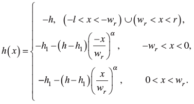
Here, $h_1$ is the gap between the center of the sill and mean free surface ( $z=0$ ), and $l$ and $r$ are the left and right far-field boundaries, respectively. In general, these far-field boundaries are located two to three times far away from the breakwater system. Depending on the parameter $\alpha$, the shape of the sill profile will change, i.e. $\alpha=1.0$ corresponds to the triangular sill, $\alpha=2.0$ corresponds to the parabolic sill, and $\alpha=\infty$ corresponds to the rectangular sill [19].
The convergence of the numerical solutions based on the BEM depends on the panel size, which is used to discretize the boundaries of the domain. The panel size is expressed as ([26,27])
$p_s=\frac{1}{\kappa k_0},$
where $\kappa$ is a proportionality constant that can be obtained from the convergence analysis. Table 1 shows the convergence of the numerical solutions based on BEM for the present problem for various porosities of the floating breakwater. It is seen that for $\kappa \geq 20$, the values of the reflection coefficient $K_R$ and transmission coefficient $K_T$ converge up to four decimal places. Therefore, for the sake of convergence of the present numerical results, the panel size $P_s$ is taken with $\kappa=20$ for the computational purpose.
| Î = 0.05 | Î = 0.15 | Î = 0.25 | Î = 0.35 | ||||
k | KR | KT | KR | KT | KR | KT | KR | KT |
5 | 0.80187 | 0.50989 | 0.70546 | 0.53701 | 0.62195 | 0.55881 | 0.54669 | 0.57479 |
10 | 0.79957 | 0.52031 | 0.70418 | 0.54719 | 0.62045 | 0.56913 | 0.54437 | 0.58551 |
20 | 0.79854 | 0.52349 | 0.70320 | 0.55362 | 0.61866 | 0.57277 | 0.54259 | 0.59246 |
30 | 0.79856 | 0.52347 | 0.70320 | 0.55364 | 0.61864 | 0.57276 | 0.54250 | 0.59249 |
In Figs. 3(a)-(d), $K_r, E_{\text {loss }}, F_x$, and $F_z$ versus $k_0 h$ (the nondimensional wavenumber) are plotted for the various angle of incidence. Figure 3(a) depicts that the reflection coefficient $K_r$ increases with an increase in $\theta$. Further, with an increase in $k_0 h, K_r$ reaches the global maximum and then starts to decrease and reaches the global minima. The global minima shift toward the right for larger values of the angle of incidence $\theta$. Figure 3(b) shows that the energy loss coefficient $E_{\text {loss }}$ increases with an increase in the angle of incidence $\theta$ for $0.5
In Figs. 4(a)-(d), $K_r, K_t, E_{\text {loss }}$, and $F_x$ are plotted as a function of the nondimensional wavenumber $k_0 h$ for various seabed profiles. It is observed that the effects of bottom topography on $K_r, K_t, E_{\text {Loss }}$, and $F_x$ are insignificant in the shortwave regime. However, in the longwave regime, the reflection coefficient $K_r$ takes the higher values as $\alpha \rightarrow \infty$, i.e. for rectangular sill. Figure 4(b) shows that $K_t$ decreases as $\alpha \rightarrow \infty$ for $0
In Figs. 5(a)-(e), $K_r, K_t, E_{\text {loss }}, F_z$ and $F_x$ versus $w_1 / \lambda$ ( $\lambda$ is the wavelength corresponding to the incoming wave) are plotted for distinct submergence drafts of the breakwater system. It is observed that $K_r, K_t, E_{\text {loss }}, F_x$ and $F_z$ follow a periodic oscillatory trend as $w_1 / \lambda$ increases. This periodic nature is due to the formation of standing waves in the region between the slatted screens and the porous structure. Figure 5 (a) shows that $K_r$ reduces as the submergence depth of the breakwater system increases. This happens due to the fact that a major part of the incident wave energy is attenuated by the porous breakwater system, as seen in Fig. 5(c). Figure 5(b) depicts that $K_t$ decreases significantly with an increase in the submergence draft of the porous breakwater system. It is seen that $\geq 98 \%$ of the incident wave energy is attenuated with $20 \%$ porosity of screens and having submergence draft $d=0.65 h$, and $15 \%$ porosity of the porous rectangular structure in the presence of parabolic sill. Further, Fig. 5(d) depicts that the dimensionless vertical force $F_z$ reduces with an increase in the submergence depth of the breakwater system. However, contradictory behavior is observed in the case of the horizontal force $F_x$. This happens as the incident waves will hit over more areas of the slotted screens with an increase in the submergence depth. In both Figs. 5(d) and (e), the maximum wave forces are observed within the vicinity of $w_1 / \lambda \approx n / 2, n=1,2,3, \ldots$ and the minimum wave forces acting on the porous rectangular structure are observed within the vicinity of $(n-1) / 2
Using eqn (20), the time-dependent free surface elevation $\zeta(x, t)$ in regions $1,2,3$, and 4 is obtained using the following Fourier integral:
where
$F(\sigma)=\sqrt{\frac{b}{\pi}} \exp \left(-b\left(\sigma-\sigma_0\right)\right)^2$
is the FT (Fourier transform) of the incident pulse with $b$ being the scale factor and $\sigma_0$ being the central frequency of the incident pulse. Further, $\eta(x, \sigma)$ is the frequency-dependent free surface elevation in regions $1,2,3$, and 4 . The time-dependent motion is shown in Figs. 6(a)(g) for a different time. In all the figures, it is observed that a mixed interference contains the mix of both constructive and destructive interference due to the interaction of reflected waves by breakwater system and seabed undulation at various points. Since the interacting waves do not have the same wavelength, it is observed that occurrence of the constructive interference at some points and the occurrence of the destructive interference at some other points. The results show an irregular wave pattern in the seaside of the breakwater for waves with small and large wave periods. On the contrary, the resonance phenomena are observed due to the interaction between the incident and high-amplitude reflected waves by the breakwater system and seabed undulation.
6. Conclusions
An iterative BEM-based numerical solution approach has been introduced to analyze the effectiveness of porous floating breakwater with slotted screens over a sill-type bottom topography. The scattering coefficients such as the reflection and transmission coefficients, energy loss coefficient, and wave loads acting on the breakwater system are analyzed based on the linear wave-structure interaction theory. Moreover, the numerical results show a good agreement between the present results and the results of Abul-Azm and Gesraha [23] for the oblique wave scattering by a rigid rectangular floating breakwater over a horizontal seabed. The results depict that
- The scattering coefficients and wave forces on the floating porous breakwater system show a periodic oscillatory pattern as $w_1 / \lambda$ varies.
- The reflection coefficient increases with an increase in the angle of incidence in the longwave regime. In case of normal incidence, $\geq 90 \%$ of the incident wave energy is attenuated with $20 \%$ porosities of the slotted screens and $15 \%$ porosity of the porous structure for a certain range of wave frequencies when the breakwater system is floating over a parabolic sill-type bottom, especially, for intermediate and shortwave regimes.
- Due to the presence of the slotted screens with moderate porosity, the wave load intensity on the rectangular porous structure reduces.
- The maximum wave forces are observed when $w_1 / \lambda \approx n / 2, n=1,2,3, \ldots$, and the minimum wave forces acting on the porous rectangular structure are observed in the intermediate points $(n-1) / 2 - The maximum wave reflection and minimum wave transmission are noticed for porous breakwater systems with rectangular sill-type bottom profiles, in particular, for long waves. Therefore, the proposed porous breakwater design helps to create the required tranquility zone in harbors by restricting the wave transmission and reducing the wave loads on the breakwater. Further, the present solution method can be extended to deal with various problems that arise in ocean and harbor engineering.
The data used to support the findings of this study are available from the corresponding author upon request.
SK acknowledges the financial support received through the DST project: DST/ INSPIRE/04/2017/002460 to pursue this research work. Further, supports were received from BITS-Pilani, Hyderabad Campus through BITS/GAU/RIG/2019/H0631 and BITS/ GAU/ACRG/2019/H0631 (Additional Competitive Research Grant) projects. SK and KP acknowledge DST, New Delhi, India, for providing facilities through DST-FIST lab, Depart- ment of Mathematics, BITS-Pilani, Hyderabad Campus, where this work is done.
The authors declare that they have no conflicts of interest.