Javascript is required
[1] Berger, B., Vorrichtung zum bediisen der oberflache eines bandes sowie bandbearbei- tungsanlage, October 18 2012. DE Patent App. DE201,110,002,017.
[2] Mohan Kumar, C., Elsen, P., Berger, B. & Janoske, U., Rotating impinging jets for surface cleaning of metals: Mathematical modeling and experimental investigation. Journal of Water Proc-cessing Engineering, Elsevier, submitted.
[3] Holmberg, K., A concept for friction mechanisms of coated surfaces. Surface and Coat- ing Technology, 56, pp. 1–10, 1992. [Crossref]
[4] Brackbill, J.U., Kothe, D.B. & Zemach, C., A continuum method for modeling surface tension. Journal of Computational Physics, 100(2), pp. 335–354, 1992. [Crossref]
[5] Berberovic, E., Hinsberg, N.V., Jakirlic, S., Roisman, I. & Tropea, C., Drop impact onto a liquid layer of finite thickness: Dynamics of the cavity evolution. Physical Review E, 79(3), 2009. [Crossref]
[6] Weller, H.G., A new approach to vof-based interface capturing methods for incompress- ible and compressible flows. Technical report, 2008.
[7] Hirt, C.W. & Nichols, B.D., Volume of fluid (VOF) method for the dynamics of free boundaries. Journal of Computational Physics, 39(1), pp. 201–225, 1981. [Crossref]
[8] Rusche, H., Computational fluid dynamics of dispersed two-phase flows at high phase fractions. PhD thesis, Imperial college of science, Technology and Medicine, London, 2002.
[9] Wilcox, D.C., Turbulence modeling for CFD. DCW Industries, Inc. c1994, La Cnada, CA, 1994.
[10] OpenFOAM Foundation. OpenFOAM C+ + Documentation.
[11] Georgiadou, M., Mohr, R. & Alkire, R.C., Local mass transport in two-dimensional cavities in laminar shear flow. Journal of The Electrochemical Society, 147(8), pp. 3021–3028, 2000.
Search

Acadlore takes over the publication of IJCMEM from 2025 Vol. 13, No. 3. The preceding volumes were published under a CC BY 4.0 license by the previous owner, and displayed here as agreed between Acadlore and the previous owner. ✯ : This issue/volume is not published by Acadlore.

Open Access
Research article

Numerical Modeling and Analysis of Viscous Media Removal from Grooved Surfaces with Rotating Impinging Jets

c. mohan kumar1,2,
p. elsen3,
b. berger4,
u. janoske1
1
University of Wuppertal, Germany
2
Baden-Wuerttemberg Cooperative State University, Mosbach, Germany
3
Breuer GmbH, Germany
4
Bernd-Berger Consulting, Germany
International Journal of Computational Methods and Experimental Measurements
|
Volume 4, Issue 4, 2016
|
Pages 573-582
Received: N/A,
Revised: N/A,
Accepted: N/A,
Available online: 11-29-2016
View Full Article|Download PDF

Abstract:

Surface cleaning prior to coating and fabrication processes is an important process to ensure the quality and proper functioning of the products. The current work involves the modeling of a cleaning process where viscous media is removed from surfaces using mechanical force from impinging water jets. The jets are mounted on a rotating nozzle carrier, which combine the normal force with increased tangential force resulting in the removal of oil present in the grooves of metal surfaces.

The modeling of such a process is performed with the volume of fluid (VOF) method with an open source Computational Fluid Dynamics (CFD) code Open-FOAM®. Rectangular grooves, which represent an idealized form of roughness are considered for numerical analysis. The oil present in the roughness grooves is resolved by the computational mesh.

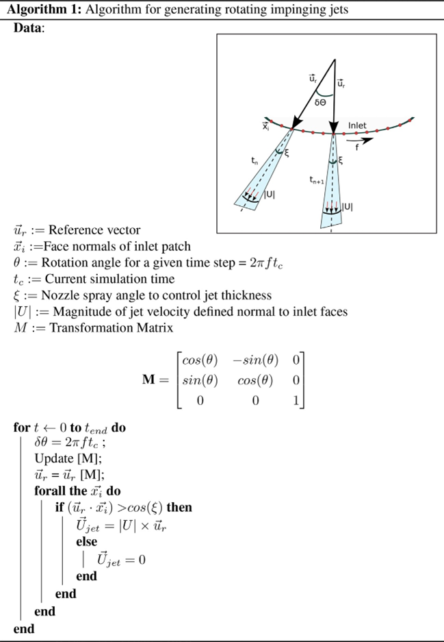
The inlet is modified to model the phenomenon of rotating jets. In order to model the effect of rotating jets, a reference vector is transformed by a time-dependent rotational tensor. All the faces which make a certain angle (opening angle) with the reference vector are activated. This results in the formation of jets with a thickness which can be controlled by the opening angle. The numerical model is used to study the influence of the frequency of rotation, nozzle exit velocity, viscosity of oil and the aspect ratio of the grooves on surface cleaning. An impinging turbulent jet is modeled using the k-epsilon turbulence model.

Finally, the CFD simulations are qualitatively compared with a previously developed semi-empirical model and experiments conducted in an industrial setup. The tendencies of oil removal due to the effect of the process parameters observed in the simulation are in close agreement with the semi-empirical model and experimental results. Thus, the cleaning model can be used to conduct sensitivity analysis to achieve an optimal performance of the cleaning process.

Keywords: CFD, Jets, Surface cleaning, Volume of fluid

1. Introduction

Impinging jets are widely used for surface cleaning industries for its higher mass transfer capabilities. Due to the normal stresses from impact, the jet penetrates the contaminant layer and displaces the contaminants. The ensuing shear flow removes unwanted substances out of the surface to be cleaned. Primary cleaning methods can be classified as water based, solvent based and chemical based. The latter two processes, though widely used in the surface cleaning industry involves the use of Volatile Organic Compounds (VOC) which are hazardous to the environment. Conventional cleaning processes with water jets involve multiple nozzles mounted in series on a stationary nozzle head where the surface to be cleaned traverses under the nozzle head. The drawback of such a process is the increased water consumption and the demand for a high pressure head before the nozzles since all the nozzles are active at all times. The concept in this work involves mounting nozzles around a rotating nozzle head.

A feed system is constructed in order to activate a certain number of nozzles with water, which make a certain angle with respect to the normal direction. The schematic of the prototype built by Breuer GmbH, Solingen is shown in Fig. 1. The inset of the figure shows the rotating nozzle head with nozzles mounted in an elliptical path. The idea follows the patent by Berger [1]. Water is used as the cleaning fluid without additional solvents or chemicals. The surface to be cleaned is placed on a conveyor belt and traverses at a controlled speed under the rotating nozzle head ensuring a clean surface. The cleaning process has no process downtimes since it can be categorized as a Cleaning In Place (CIP) process.

The current work involves two dimensional modeling of such a system with the help of Computational Fluid Dynamics (CFD) in order to study the effect of various influencing parameters like the jet velocity, viscosity of the viscous layer present on the surface, total contact time of cleaning, which is influenced by the sheet speed, which is the speed at which the surface traverses and the frequency of rotation of the rotating head. Additionally, the influence of the aspect ratio of the grooves on film removal is also analyzed.

In our previous studies, a semi-empirical model for such a scenario has been developed and validated from experiments [2]. It bases itself upon the contact time of the interacting fluid with the surface to be cleaned. The removal rate during each impingement is related to the process parameters like pump pressure, oil viscosity present in the grooves, sheet speed and rotation frequency. The model will be briefly mentioned here. The reader is directed to the cited article for further details of the model and the experiments conducted. The relation for total contact time for a sheet moving at a speed of $v_s$ and the nozzle carrier rotating at a frequency $f$, after simplifications result in,

Figure 1
$t_c=\frac{\beta d_N}{2 \pi v_s}$
(1)

Here, the simplification is, $\frac{v_s}{v_w} \ll 1$, where $v_w$ is the circumferential velocity of the rotating water jet and $v_s$ is the sheet speed. Further, the rate of removal $\alpha$ decreases with an increase in the number of impingements since more work need to be expended as the height of oil layer reduces [3]. Let $\alpha_1$ be the amount of oil removed after first impingement. Let us assume that, the amount of oil removed in subsequent impingements decays with the number of impingements.

$\alpha_i=\frac{1}{n} \alpha_1, \forall i \in(2, n)$
(2)

$n$ is the number of impingements during the cleaning process. Further mathematical transformations and modeling results in the final residual mass of oil,

$m_{\text {res }}=[\underbrace{1-\left(\frac{P_{p m p}}{P_T}\right)\left(\frac{v_{\text {jet }}}{v_{\text {oil }}}\right)}_{\alpha 1} \underbrace{\left[\ln \left(\frac{r f \beta}{v_s}\right)+\varepsilon_n\right]}_{\theta(n)}] m_{\text {oil }}$
(3)

$\theta(n)$ is a discrete harmonic function which diverges with increasing $n$. It is an approximation of the partial sum of the series with Taylor expansion. $P_T$ is an empirical constant and $\varepsilon_n$ is the residual error. $m_{\text {res }}$ and $m_{\text {oil }}$ are the residual oil mass after cleaning and initial coated oil mass, respectively. $v_{\text {jet }}$ and $v_{\text {oil }}$ are the kinematic viscosity of water jet and deposited oil. $P_{p m p}$ is the pump pressure. $f$ is the frequency of rotation of the nozzle head and $\beta$ in radians, is the angle to control the opening arc length where the nozzles are active when they make an angle with the normal of the surface to be cleaned.

2. Modeling of the Cleaning Process

The cleaning process is modeled with the Volume of fluid (VOF) method which is an interface tracking method. The open-source code for CFD simulations Open-FOAM® where VOF is implemented is used for the simulations. The method and implemented algorithms are exhaustively discussed in [4–8] and will not be explicitly discussed here.

The simulation domain is as shown in Fig. 2. The inlet patch is the surface where water jet enters the domain. The water jet is active only a fraction of the inlet patch and moves across the patch with the specified frequency of rotation. A velocity-inlet boundary condition is chosen for the inlet with some modifications to account for jet rotation explained subsequently. The walls are subjected to a no-slip boundary condition. The atmosphere patch works as an outlet patch allowing the flux to exit the simulation domain. At the start of the simulation the complete domain is filled with air excluding the region of grooves which contain oil. Oil fraction in grooves is recorded at every time step. In order to analyze the effect of frequency and contact time on removal rate ()α, a stationary rough sheet is considered and frequencies in the range of 2–20 Hz are simulated. The width of each groove is 1 mm and 8 grooves are considered on the surface for simulation.

Figure 2. Simulation domain for simulation

To simulate the effect of rotating jets, the jet inlet in the simulation domain is modified. An algorithm which transforms the jet along the inlet patch based on rotation frequency is developed. The algorithm is shown in Algorithm 1

The idea is to begin with a reference vector $\vec{u}_r$ which is rotated based on rotation angle $\delta \theta$. The rotation angle is calculated from the current time step $\delta t$ and the frequency of rotation f . The values for air and oil fraction are set to zero at all times during the simulation. The face normals inlet which make a certain angle, defined by $\xi$ are made active by setting the value of water fraction to 1 . A velocity inlet condition is used for the inlet. This results in the generation of a water jet only from the active inlet faces. The rotation angle subsequently changes with increase in time steps, resulting in a change in reference vector $\vec{u}_r$, thus generating rotating impinging jets. Thus, all the influencing parameters can be simulated and their effects can be analyzed

3. Numerical Simulation and Case Setup

The following assumptions are made for the numerical simulation;

  • All media; water, oil and air are immiscible and incompressible.

  • Two dimensional and Isothermal.

  • Coated oil is Newtonian.

  • Water phase assumed to be continuous.

  • Turbulent jets.

  • A quiescent atmosphere

  • No adhesion between the film layer and the substrate

The standoff distance between the inlet and the surface of the grooves is 30 mm . The mesh size was in the range of 45,000 to 48,000 cells. The mesh was fine in the cleaning region in comparison with the mesh near the outlet patches. Standard k -epsilon model [9] was used for modeling turbulent jets. A $y^{+}$value between 30 and 300 was maintained for all simulations.

The boundary conditions for the simulations are shown in Table 1. It is based on velocity inlet and pressure outlet conditions. The modified inlet (Algorithm 1) is used for velocity at the inlet. A condition which considers buoyancy effects, fixedFluxPressure [10] defined in OpenFOAM® is used for pressure at the walls. Remaining faces of the domain follow the conventional boundary conditions.

The influence of the following parameters are studied.

  1. Jet exit velocity, $U_{j e t}$

  2. Kinematic viscosity of oil in grooves, $v_{\text {oil }}$

  3. Frequency of jet rotation, $f$

  4. Aspect ratio of grooves, $a_r=h / w, \mathrm{~h}$ is the height and w is the width of the grooves

Table 1. Boundary conditions used for simulation, c is the corresponding flow field

Field

Inlet

Atmosphere

Walls

Water fraction

c = 1

Ñc = 0

Ñc = 0

Air fraction

c = 0

Ñc = 0

Ñc = 0

Oil fraction

c = 0

Ñc = 0

Ñc = 0

Velocity

Modified (c.f. Algorithm 1)

Ñc = 0

c = 0

Pressure

Ñc = 0

c = constant

Ñc = k

K

c = constant

Ñc = 0

wall function

є

c = constant

Ñc = 0

wall function

4. Results and Discussion

Figure 3 shows the simulation sequence of the modeled oil removal process with a rotating impinging jet at $60 \mathrm{~m} \mathrm{~s}^{-1}$ inlet velocity with a frequency of 10 Hz . The kinematic viscosity of the oil in grooves is $20 \mathrm{~mm}^2 / \mathrm{s}$. The aspect ratio of the grooves is 3 . Two removal modes are observed. The first mode is the penetration of water jet through the oil layer and the second mode is the transport of oil outward of the grooves due to shear stress and recirculation. The rotating jet enhances the shear stress consequently enhancing the recirculation resulting in an increased removal rate.

Subsequent analysis of simulated results has been done for the state of residual oil present in grooves after three impingements. Figure 4 depicts the influence of jet velocity on residual oil fraction. With increasing velocity, the residual fraction reduces as expected. It is due to higher penetration of the jet into the grooves displacing the oil, eventually removing it.

Figure 3. Simulation of oil removal process from rotating impinging jets. Frequency $=10 \mathrm{~Hz}$, $v_{\text {oil }}=50 \mathrm{~mm}^2 / \mathrm{s}, U_{\text {jet }}=60 \mathrm{~ms}^{-1}, a_r=3$. Left: Velocity field of the impinging jet, Right: Removal of oil from the grooves, during one rotation of the nozzle carrier
Figure 4. Influence jet velocity, corresponding pump pressure on residual oil mass fraction. Frequency $=10 \mathrm{~Hz}, v_{\text {oil }}=50 \mathrm{~mm}^2 / \mathrm{s}, a_r=1$

The influence of viscosity of oil present in grooves is shown in Fig. 5. It is seen that the simulated results do not have a smooth pattern. Although the tendency of the simulated results increase in aspect ratio, multiple vortices develop thus localizing the recirculation region. The observed tendency repeats for all 3 impingements. The residual oil fraction thus increases with increase in aspect ratio of grooves.

The absence of adhesion effects near the wall and a few number of impingements simulated in comparison with the valid range of residual model hinders the direct comparison of frequency influence of numerical simulations with the residual oil model. Therefore, the influence of a number of impingements correspondingly total contact time, is compared. Figure 7 compares eqn (2) with the simulations. The amount of removed oil fraction is plotted with impingement number. The simulation results for various rotation frequencies follow the reciprocal behavior of removed oil fraction during each impingement with an increase in the number of impingements.

Figure 5. Influence of oil viscosity in grooves on residual oil mass fraction. Frequency $=10 \mathrm{Hz}, v_{\text {oil }}=20 \mathrm{~mm}^2 / \mathrm{s}, U_{\text {jet }}=60 \mathrm{~ms}^{-1}, a_r=1$
Figure 6. Influence of groove aspect ratio on residual oil mass fraction. Frequency $=10 \mathrm{~Hz}$, $v_{\text {oil }}=50 \mathrm{~mm}^2 / \mathrm{s}, U_{\text {jet }}=60 \mathrm{~ms}^{-1}$
Figure 7. Removed oil fraction behavior with impingement number for different rotation frequency. $\mathrm{v}_{\text {oil }}=50 \mathrm{~mm}^2 / \mathrm{s}, U j_{e t}=60 \mathrm{~ms}^{-1}, a_r=1$

5. Conclusions

Numerical modeling and simulation of a novel cleaning process has been performed. An algorithm to generate a rotating impinging jet at the inlet of the domain has been developed. The tendencies observed in the sensitivity of residual oil mass fraction subjected to a combination of process parameters are well captured in the numerical simulations. The influence of the aspect ratio of cleaning behavior provides an insight into the flow dynamics of the oil removal mechanism in the grooves.

This work provides a fundamental platform for simulating surface cleaning with moving nozzle carrier heads. There are further improvements necessary in order to conduct simulations closer to reality. A three dimensional simulation of the process can be performed with a surface composed of heterogenous grooves with a Gaussian distribution of aspect ratios which represents a more realistic surface topology. Further, a function for the residual oil fraction based on the groove aspect ratio can be developed and its effects can be modeled as a source term along with wall adhesion to include roughness effects, reducing computational time which is the focus of our subsequent work.

Data Availability

The data used to support the findings of this study are available from the corresponding author upon request.

Acknowledgments

The current work with the serial number KF2168632SU3 is financially supported by the Federal Ministry for Economic Affairs and Energy under Arbeitsgemein-schaft Industrieller Forschungsvereinigungen (AIF), Berlin in correspondence with the decision made by the Federal government of Germany.

Conflicts of Interest

The authors declare that they have no conflicts of interest.

References
[1] Berger, B., Vorrichtung zum bediisen der oberflache eines bandes sowie bandbearbei- tungsanlage, October 18 2012. DE Patent App. DE201,110,002,017.
[2] Mohan Kumar, C., Elsen, P., Berger, B. & Janoske, U., Rotating impinging jets for surface cleaning of metals: Mathematical modeling and experimental investigation. Journal of Water Proc-cessing Engineering, Elsevier, submitted.
[3] Holmberg, K., A concept for friction mechanisms of coated surfaces. Surface and Coat- ing Technology, 56, pp. 1–10, 1992. [Crossref]
[4] Brackbill, J.U., Kothe, D.B. & Zemach, C., A continuum method for modeling surface tension. Journal of Computational Physics, 100(2), pp. 335–354, 1992. [Crossref]
[5] Berberovic, E., Hinsberg, N.V., Jakirlic, S., Roisman, I. & Tropea, C., Drop impact onto a liquid layer of finite thickness: Dynamics of the cavity evolution. Physical Review E, 79(3), 2009. [Crossref]
[6] Weller, H.G., A new approach to vof-based interface capturing methods for incompress- ible and compressible flows. Technical report, 2008.
[7] Hirt, C.W. & Nichols, B.D., Volume of fluid (VOF) method for the dynamics of free boundaries. Journal of Computational Physics, 39(1), pp. 201–225, 1981. [Crossref]
[8] Rusche, H., Computational fluid dynamics of dispersed two-phase flows at high phase fractions. PhD thesis, Imperial college of science, Technology and Medicine, London, 2002.
[9] Wilcox, D.C., Turbulence modeling for CFD. DCW Industries, Inc. c1994, La Cnada, CA, 1994.
[10] OpenFOAM Foundation. OpenFOAM C+ + Documentation.
[11] Georgiadou, M., Mohr, R. & Alkire, R.C., Local mass transport in two-dimensional cavities in laminar shear flow. Journal of The Electrochemical Society, 147(8), pp. 3021–3028, 2000.

Cite this:
APA Style
IEEE Style
BibTex Style
MLA Style
Chicago Style
GB-T-7714-2015
Kumar, C. M., Elsen, P., Berger, B., & Janoske, U. (2016). Numerical Modeling and Analysis of Viscous Media Removal from Grooved Surfaces with Rotating Impinging Jets. Int. J. Comput. Methods Exp. Meas., 4(4), 573-582. https://doi.org/10.2495/CMEM-V4-N4-573-582
C. M. Kumar, P. Elsen, B. Berger, and U. Janoske, "Numerical Modeling and Analysis of Viscous Media Removal from Grooved Surfaces with Rotating Impinging Jets," Int. J. Comput. Methods Exp. Meas., vol. 4, no. 4, pp. 573-582, 2016. https://doi.org/10.2495/CMEM-V4-N4-573-582
@research-article{Kumar2016NumericalMA,
title={Numerical Modeling and Analysis of Viscous Media Removal from Grooved Surfaces with Rotating Impinging Jets},
author={C. Mohan Kumar and P. Elsen and B. Berger and U. Janoske},
journal={International Journal of Computational Methods and Experimental Measurements},
year={2016},
page={573-582},
doi={https://doi.org/10.2495/CMEM-V4-N4-573-582}
}
C. Mohan Kumar, et al. "Numerical Modeling and Analysis of Viscous Media Removal from Grooved Surfaces with Rotating Impinging Jets." International Journal of Computational Methods and Experimental Measurements, v 4, pp 573-582. doi: https://doi.org/10.2495/CMEM-V4-N4-573-582
C. Mohan Kumar, P. Elsen, B. Berger and U. Janoske. "Numerical Modeling and Analysis of Viscous Media Removal from Grooved Surfaces with Rotating Impinging Jets." International Journal of Computational Methods and Experimental Measurements, 4, (2016): 573-582. doi: https://doi.org/10.2495/CMEM-V4-N4-573-582
KUMAR C M, ELSEN P, BERGER B, et al. Numerical Modeling and Analysis of Viscous Media Removal from Grooved Surfaces with Rotating Impinging Jets[J]. International Journal of Computational Methods and Experimental Measurements, 2016, 4(4): 573-582. https://doi.org/10.2495/CMEM-V4-N4-573-582