Acadlore takes over the publication of IJCMEM from 2025 Vol. 13, No. 3. The preceding volumes were published under a CC BY 4.0 license by the previous owner, and displayed here as agreed between Acadlore and the previous owner. ✯ : This issue/volume is not published by Acadlore.
Performance Enhancement of a Valveless Pump Driven by a Noble Piezoelectric Composite Actuator
Abstract:
This paper presents a computational and experimental study of a valveless pump driven by a noble piezoelectric composite actuator consisting of a bimorph piezoelectric plate and a metal cap. The superiority of deformation performance of the proposed composite actuator was demonstrated computationally through finite element simulation and was then verified experimentally by deflection measurements of a disc-shaped prototype under an alternating electric field. The proposed composite actuator was applied to a valveless pump in a Y-shaped fluid channel. The pump’s performance was estimated using a piezoelectric-fluid interaction finite element simulation. The effect of the fluid channel configuration was investigated, and the liquid feed volume is discussed and compared with that of conventional actuators.
1. Introduction
Micropumps, which were initially developed in 1980, have received considerable attention and played an important role in the development of microfluidics systems [1]. Micropumps are extensively used in inkjet printers, but their application is expanding into chemical, medical, and biological devices. These devices handle microliquids and are integrated into chemical analysis and microdosage systems, which are called micro-TAS or BioMEMS. Hitherto, micropumps have been developed with various working principles, such as electroelasticity, shape memory, electromagneticity, and piezoelectricity [2].
Piezoelectric actuation has advantages such as low-power consumption, reliability, and energy effi ciency. The fi rst piezoelectric valveless pump was developed in 1993 [3]. Since then, many valveless pumps driven by piezoelectric actuators have been studied [3], [4], [5], [6], [7], [8], [9], [10], [11], [12], [13] because they can be easily incorporated into microfl uidics systems. Their pumping performance depends on the fl ow channel topology design and on the piezoelectric actuator. Based on the fl ow channel, most valveless pumps can be classified into one of two types. The first has vertical fl ow channels with respect to a plate-shaped piezoelectric actuator and chamber [3], [4], [5], [6]. In this type of valveless pump, two fl ow-directing valves are replaced by two diffuser/nozzle channels. A diffuser is an expanding duct, and a nozzle is a converging duct. The diffuser/nozzle channel is geometrically designed to have a lower pressure loss in the diffuser direction than in the nozzle direction. As the chamber volume increases, the inlet acts as a diffuser with a lower fl ow restriction than the outlet, which acts as a nozzle. On the other hand, as the chamber volume decreases, the outlet acts as a diffuser with a lower fl ow restriction than the inlet, which acts as a nozzle. The second type of valveless pump has horizontal flow channels connected to a plate-shaped chamber with a piezoelectric actuator [7], [8], [9], [10], [11]. A diffuser is defined as a channel with an expanding cross-sectional area in the fl ow direction, and a nozzle is a channel with a decreasing cross-sectional area in the fl ow direction. Although the pump operation is same as with the former type, the latter has a thin structure, which is advantageous for miniaturization. To improve the pumping performance of a valveless pump, the geometry of the diffuser/nozzle channels has been improved [12], [13]. Furthermore, several piezoelectric-actuated chambers can be connected in series and/or parallel for enhanced performance [14], [15].
Piezoelectric actuators can also be classified into two types. The first is the monomorph actuator, which has been used in various valveless pumps [3], [4], [5], [6], [7], [8], [9], [10], [11]. The monomorph actuator consists of a piezoelectric ceramic plate and a thin metal plate, and is deflected by the difference in in-plane strain between these two plates. The other type of actuator is the bimorph actuator, which is composed of two thin piezoelectric ceramic plates bonded together. The bimorph actuator, which has also been used in many valveless pumps [16], [17], [18], reverses the deformation of two piezoelectric plates by opposite electric field or opposite remanent polarization. Namely, the opposite sign of in-plane strain between the two piezoelectric plates can generate a large deflection in out-of-plane direction. To amplify the displacement of piezoelectric actuators, a composite actuator called the ‘Moonie’ was designed and fabricated [19], [20], [21]. This was a piezoelectric actuator bonded to a metal cap. The Moonie actuator deforms the metal cap by utilizing the in-plane displacement generated by the piezoelectric actuator. Moonie actuators were followed by many advanced topology designs and improvements in the geometry and confi guration of the metal cap [22], [23]. Hitherto, only simple piezoelectric structures have been employed in Moonie actuators, even though the bimorph structure would enable the generation of larger in-plane displacements. The potentially superior bimorph Moonie actuator has not been investigated, and composite actuators have not yet been utilized in micropumps.
Consequently, the objective of this work was the examination of a noble composite actuator consisting of a piezoelectric bimorph actuator and a metal cap, and its application to the valveless pump. We call this new actuator design the ‘new Moonie actuator’. In our previous work [24], the superiority of the proposed composite actuator to conventional ones at the view point of static deflection was verified through finite element simulations. In the present work, the dynamic deflection of the proposed composite actuator was examined experimentally. The proposed actuator was applied to a valveless pump with a Y-shaped fluid channel [18], and the pumping performance was investigated through piezoelectric–fluid interaction finite element simulation.
2. Performance Verification of the New Moonie Actuator
Table 1 compares the configuration and deformation behavior of four piezoelectric actuators. If the $x_1-x_2-x_3$ orthogonal coordinate system in Table 1 is employed, $x_1$ and $x_2$ indicate the inplane direction and $x_3$ is the thickness direction of piezoelectric plate. The first is a simple piezoelectric plate, which is called a simple actuator in this paper. When a positive electric field ($E_3$) is applied in the thickness direction of the simple actuator, it extends in the thickness direction and contracts in the in-plane directions. Based on the piezoelectric strain constant $d_{m i j}$, the mechanical strains $\varepsilon_{33}$ and $\varepsilon_{11}\left(=\varepsilon_{22}\right)$ can be expressed as $d_{333} E_3$ and $d_{311} E_3$, respectively. In a negative electric field, the deformation is reversed. To obtain the volume change in the piezoelectric pump, the out-of-plane strain $\varepsilon_{33}$ caused by piezoelectric strain constant $d_{333}$ is utilized. The second actuator was a bimorph actuator consisting of two piezoelectric plates. This actuator generates a large deflection because of the difference between in-plane strains $\varepsilon_{11}$ and $\varepsilon_{22}$ caused by $d_{311}$ and $d_{322}$ between the upper and lower piezoelectric plates. The out-of-plane and in-plane displacements of the bimorph actuator are larger than those of the simple actuator, and deflection angle occurs at the edge of the bimorph actuator. The third and fourth actuators were the Moonie and the proposed new Moonie. Both are composite actuators consisting of a piezoelectric element and a metal cap. In the conventional Moonie actuator, the metal cap is bent by the in-plane strains caused by a simple actuator. The deflection of the metal cap can be amplified if the in-plane strains of the piezoelectric element are increased. In the proposed new Moonie actuator, a bimorph actuator, which has in-plane strains larger than those of the simple actuator, is applied to the piezoelectric element of a Moonie actuator. The new Moonie actuator can amplify the overall deflection not only because of larger in-plane strains but also by the deflection angle of its edges. With the new Moonie actuator, the metal cap is deflected on the upper side if the piezoelectric element is deflected on the lower side. By contrast, the metal cap is deflected on the lower side if the piezoelectric element is deflected on the upper side. Consequently, it is important to provide sufficient clearance for the metal cap to prevent physical interference with the piezoelectric element.
To verify the superior performance of the proposed new Moonie actuator, four prototype piezoelectric actuators were fabricated, as shown in Table 1. Figure 1 shows the dimensions of these prototypes. The piezoelectric disc was 1.8-mm thick and 10 mm in diameter. The metal cap was 0.2-mm thick and had a clearance of 0.2 mm. Before discussing the experimental results, let us review the computational results for static deformation, which we published in a previous report [24]. Figure 2 shows fi nite element models for the four piezoelectric actuators. Linear solid elements with eight nodes were employed. The material properties of the piezoelectric element and the metal cap were set to those of PZT ceramic and brass, respectively. In case of the simple actuator, the electric potential of the upper surface was set to 0.0 V, while +1.0 V was applied to the lower surface. In case of the bimorph actuator, the electric potential of the upper and lower surfaces was set to 0.0 V, while +1.0 V was applied to the middle bonded surface. The nodes at the outer edge of the bottom of the disk were fixed along the vertical direction. Figure 3 compares the deflection curves of the four actuators. The vertical axis represents deflection of the bottom surface, and the horizontal axis represents the radial distance from the center of the disc. Figure 4 compares the maximum deflections of the disc centers of the four actuators. The computational results indicated that the proposed new Moonie actuator can generate the largest deflection, and its maximum deflection was more than double that of the conventional Moonie actuator.
Simple Actuator | Bimorph Actuator | Moonie Actuator | New Moonie Actuator |
|---|---|---|---|
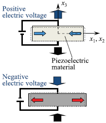 | 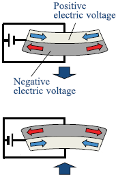 | 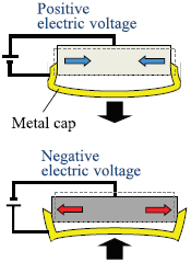 | 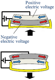 |

Figure 5 shows an overview of the dynamic deflection measurement of a piezoelectric actuator. The piezoelectric actuator was minimally fixed to an acrylic plate with scotch tape so as not to detract from its actuation performance. AC 30 V was applied, and frequency was swept from 20 Hz to 10 kHz. The maximum deflection at the center was measured using a laser Doppler vibrometer. The experimentally observed frequency response curves are shown in Figure 6. The primary resonance peak was below 2 kHz for every actuator. Figure 7 compares the maximum defl ection of the primary resonance peaks of all four piezoelectric actuators. The maximum deflections of the actuators can be arranged in the following order: simple < Moonie < bimorph < new Moonie. The maximum deflection of the new Moonie actuator was more than triple that of the conventional Moonie actuator.
3. Application to Valveless Pump
The proposed new Moonie actuator was applied to a Y-shaped fluid channel [18], and the pumping performance was evaluated using a piezoelectric–fluid interaction finite element simulation. The configuration of the Y-shaped fluid channel driven by the piezoelectric actuator is shown in Figure 8. The main and subfluid channels were 30- and 10-mm long, respectively. Both channels were 0.1-mm deep. The channel width w was 0.3 mm. The subfluid channel was connected to the center of the main fluid channel. The angle between the main and subfluid channels q was 30°. Atmospheric pressure was applied to both edges of the straight main fluid channel. There was a 10-mm-diameter chamber at the other end of the subfluid channel. The top surface of the chamber was hermetically sealed by the piezoelectric actuator. An AC voltage was applied to the piezoelectric actuator. This voltage had a peak value of 100 V at 50 Hz. The fluid was assumed to be water, which has a density of 998 kg/m3 and a viscosity of 0.89 mPa.s. All of the channels and the chamber were filled with water. Although the water-level difference between the reservoir tanks at each end of the main channel was estimated in the previous study, the objective of this research was to examine the liquid feed rate for a given length of time.
Figure 9 shows a time history of the fl ow rate at the outlet with a new Moonie actuator connected to the chamber. The flow rate changed regularly according to the piezoelectric actuation. The positive direction of fl ow was defined as left to right. The flow rate at the outlet was positive while the chamber volume increased, and negative while the chamber volume decreased. Figure 10 compares the fl ow velocity distributions of the supply and pump modes, which indicates the state at the peaks in regions A and B of Figure 9. It is noteworthy that a large vortex appears at the right side of the interfluent point. This vortex caused the observed difference between the positive and negative flow rates, and determined the pumping performance. To estimate the pumping performance quantitatively, the difference in time integration within regions A and B shown in Figure 9 was calculated for every piezoelectric actuator. Figure 11 summarizes the liquid feed volume per cycle of piezoelectric actuation, as estimated from the difference in time integration. The liquid feed volume of the new Moonie actuator was the highest of the four and was more than double that of the conventional Moonie actuator.
Parametric investigation of the Y-shaped fluid channel geometry of the new Moonie actuator was carried out using response surface methodology [25] to improve the pumping performance. The channel width w and the angle between the main and sub fluid channels q were used as design variables. w was set to 0.1, 0.3, or 0.5 mm, and q was swept from 30° to 75° at intervals of 15°. Figure 12(a) shows finite element solutions of the liquid feed volume per cycle of piezoelectric actuation. The first and second horizontal axes represent the width and angle of the channels, respectively. The vertical axis indicates the liquid feed volume, which was obtained through piezoelectric–fluid interaction finite element simulations using the same process used for Figure 11. To find the optimum geometry for maximum pumping performance, Figure 12(b) presents computational results smoothed using a second-degree polynomial model based on response surface methodology. These computations indicated that the liquid feed volume increases when both the width and angle of the channel are decreased. A maximum liquid feed volume of 1.591 nl was obtained at a channel width of 0.15 mm and a channel angle of 30°.
4. Conclusions
A new composite actuator called the ‘new Moonie’, which consists of a bimorph piezoelectric actuator and a metal cap, was examined experimentally and computationally. We obtained two remarkable results: First, dynamic deflection measurements of four different actuators indicated that the new Moonie actuator created the largest actuation, which was more than triple that of a conventional Moonie actuator. Second, when the proposed new Moonie actuator was applied to a Y-shaped fluid channel, piezoelectric–fluid interaction finite element simulations indicated that the liquid feed volume of the new Moonie actuator was the largest of those examined and was more than double that of a conventional Moonie actuator.
The data used to support the findings of this study are available from the corresponding author upon request.
The authors declare that they have no conflicts of interest.